


STP-H600/H1000 Series Instruction Manual
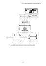
8.2 DC I/O TB3 Terminal Block
This is a terminal block for a remote input/output signal. Use it in accordance with Table
8.4 and Figure 8.4. Terminals excluding the HEATING
terminal function in either case of
the REMOTE/MANUAL operation.
The screw for the terminal is M3
*1
.
Four abbreviations are used in the following tables:
N.O :Normal Open N.C :Normal Close
IN :Input Terminal OUT :Output Terminal.
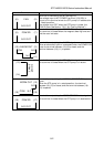
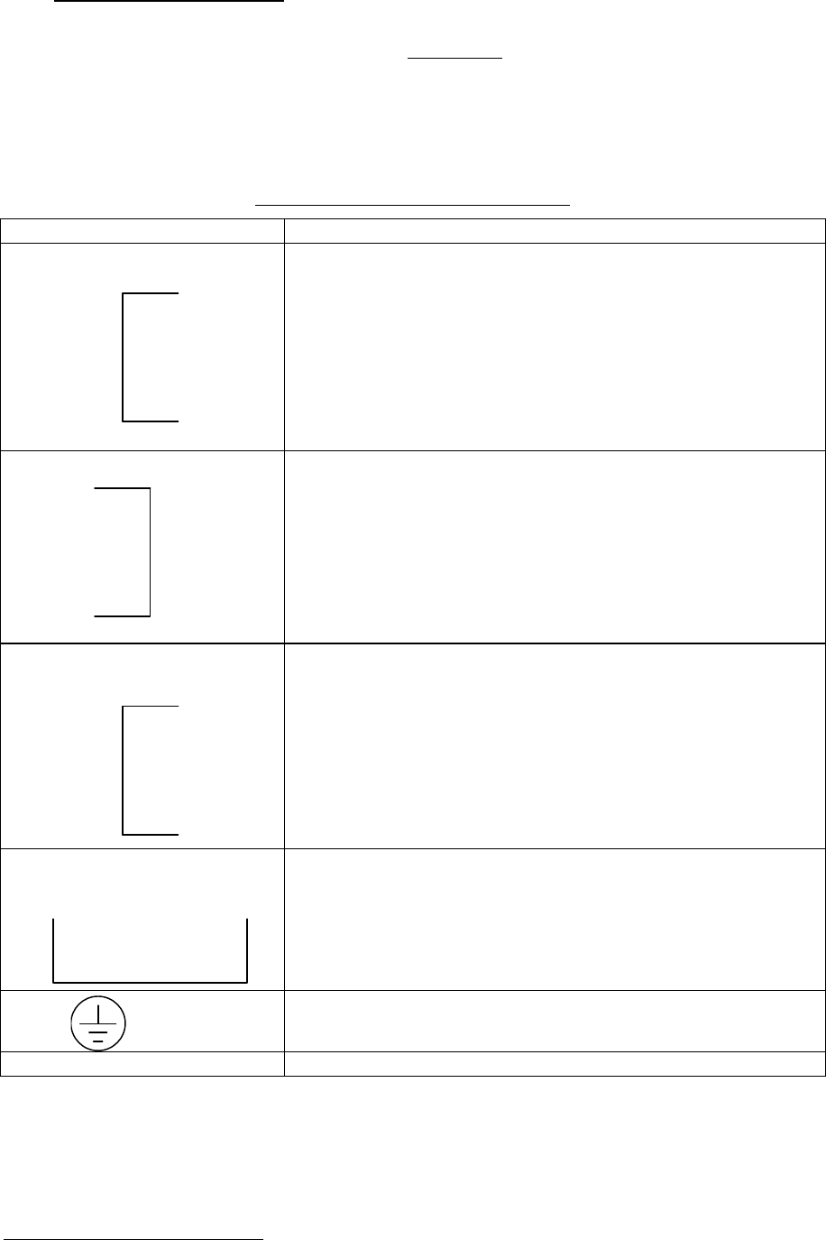
Table 8.4 DC I/O TB3 Terminal Block
Terminal Description
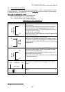
(3)
(1)
R.P THER
N.C IN
Terminal for connecting the thermal switch to protect the
auxiliary pump.
When the normal close type thermal switch for protecting
the auxiliary pump is connected between this terminal,
short the circuit between I/O TB2 R.PUMP terminal (3)-(4)
and stop the auxiliary pump.
The "FAILURE" lamp lights.
When this function is not used, short the circuit between (3)-
(4) (shorted at delivery).
(2)
(4)
HEATING
N.O IN
Terminal for baking heater remote control.
When the circuit between this terminal is shorted through
the "REMOTE" operation, the voltage for the baking heater
is output between I/O TB2 HEATER terminal (1)-(2) during
rated operation.
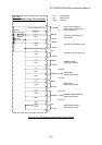
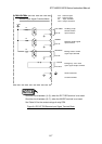
(7)
(5)
INHIBIT
N.C IN
Terminal for inputting the rotation INHIBIT signal. When
the terminal is set to open, the STP pump does not rotate
despite the STP pump operation.
And only the auxiliary pump start voltage is output to I/O
TB2 R.PUMP terminal ((3)-(4)).
When this function is not used, short the circuit between (5)-
(7) (shorted at delivery).
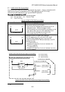
(10) (9)
N.O OUT
L.VALVE
Terminal for the emergency vent. valve operation signal.
This terminal is closed while the emergency vent. valve is
opened.
(6)
Ground
(8) Not-used
*1
: JIS
8-6