


STP-H600/H1000 Series Instruction Manual
4.3 Attaching the STP Control Unit Front Panel to a Rack
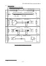
The dimensions of the STP control unit front panel conform to JIS. Therefore, this panel
can be attached to any type of commercially-available racks.
Attach the front panel unit to the rack according to the following steps:
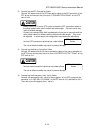
1) When attaching the front panel to a rack:
l Attach the front panel to a rack using the screw holes for the front panel.
l Also support the STP control unit from the bottom using a support angle or a similar
tool.
2) When attaching the front panel to a movable rack:
l Attach the front panel to a movable rack using the screw holes for the front panel.
l To protect the STP control unit during transport, remove the rubber foot from the
bottom and attach the STP control unit to the rack using the screw holes for the
rubber foot.
C
A
U
TI
O
N
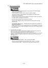
The STP control unit cannot be supported with only the screws on the front
panel (the STP control unit is a heavy product).
Always support it from the bottom. DO NOT block the ventilation port.
For the peripheral space of the STP control unit, see Figure 4.4, "Peripheral
Space of the STP Control Unit."
NOTICE
For the dimensions of the front panel and positions of screw holes for the rubber
foot, see Figure 16.2, "External Appearance of the STP Control Unit."
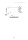
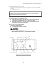
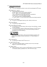
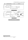
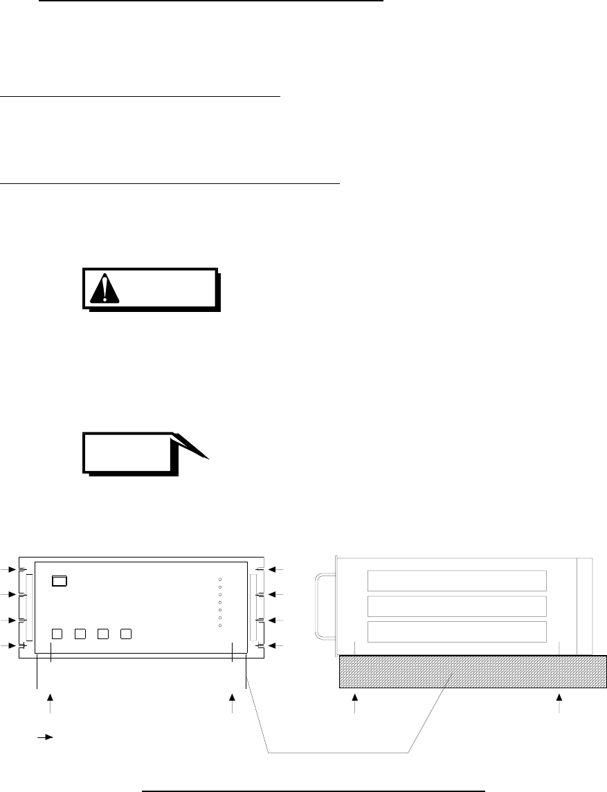
Support Angle
part: Secure with screw
Figure 4.5 Example of Securing the STP Control Unit
4-10