


STP-H600/H1000 Series Instruction Manual
3.3 How to Install the STP Pump
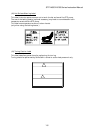
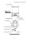
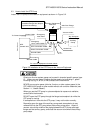
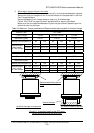
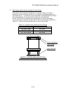
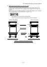
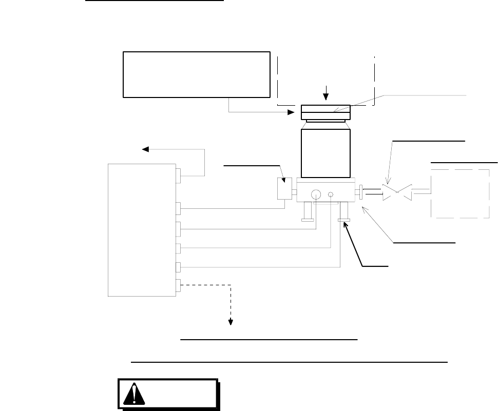
Install the STP pump to the vacuum equipment as shown in Figure 3.2.
The STP pump can be
installed through the damper
(optional accessory).
Power Cable
To Power Supply
Control Unit
Leg
Outlet Port
Pump
Dry Pump,etc.
Vacuum Valve
Inlet Port Flange
Vacuum Equipment
Inlet Port
Emergency
Vent.Valve
STP Connection Cable
Motor Connection Cable
Ground Cable
Remote Cable
To Vacuum Equipment Control Circuit
Front Panel
Auxiliary
STP
Emergency
Vent. Valve Cable
STP Pump
Figure 3.2 Installation of the STP Pump to the Vacuum Equipment
C
A
U
TI
O
N
Chlorine or fluorine system gases can be used in chemical specific pumps (type
C). When you use gases including alkaline metals, but excluding Li, gases
including Ga, Hg, In, or Sn, or HBr, contact Seiko Instruments.
NEVER use corrosive gases (chlorine, fluorine, or other system gases) in the
STP-H600/H1000 pump or other models without anti-corrosion treatment (see
Section 1.1, "Usable Gases").
When you use the STP pump in a place subjected to exposure to radiation,
contact Seiko Instruments.
DO NOT open the STP pump through the flange to atmospheric air while the
STP pump is running.
If atmospheric air flows into the STP pump, it may not function normally.
Depending upon the type of the auxiliary pump used, atmospheric air may
reverse flow into the STP pump when the auxiliary pump stops. Attach a
vacuum valve to the middle of the piping between the STP pump outlet port
flange and the auxiliary pump, and close the vacuum valve when the auxiliary
pump stops.
3-5