


STP-H600/H1000 Series Instruction Manual
8 Remote Input/Output Signal Terminal Blocks
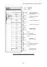
8.1 I/O TB2 Terminal Block
This is a terminal block for a remote output signal. Use it in accordance with Table 8.1 and
Figure 8.1. The terminal block functions in both the MANUAL and REMOTE operations.
The screw for the terminal is M3
*1
.
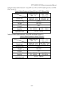
Five abbreviations are used in the following tables:
N.O :Normal Open N.C :Normal Close COM :Common
IN :Input Terminal OUT : Output Terminal
L1 :Hot N1: Neutral (or Grounded Supply)
C
A
U
TI
O
N
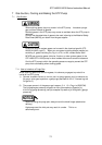
Always turn OFF the power to the remote terminal block from equipment, before
connecting/disconnecting the remote wire to the remote terminal block.
Failure to do so may result in electric shock.
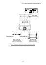
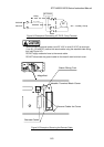
When connecting optional power (over 25 V AC or over 60 V DC) to terminals
(1) to (6), (19) and (20), secure the remote cable using the attached cable fitting
tool (see Figure 8.3).
DO NOT apply excessive force to the remote cable.
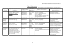
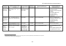
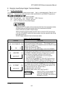
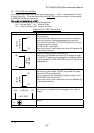
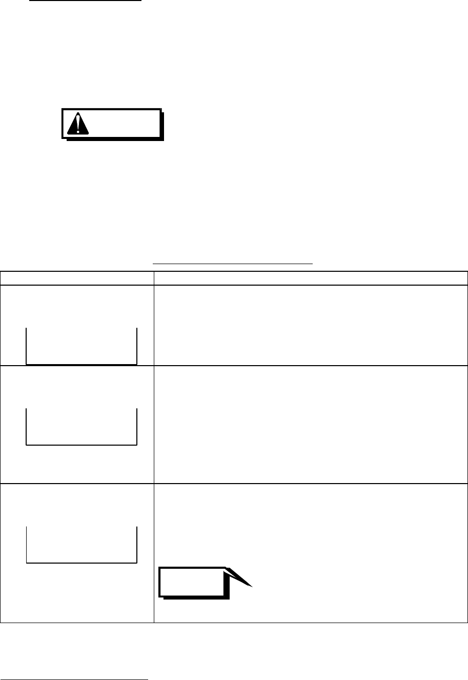
Table 8.1 I/O TB2 Terminal Block
Terminal Description
(20) (19)
L1INN1
AC.POWER
Terminal for inputting power for driving the baking heater,
auxiliary pump and air cooling unit. The voltage input to
this terminal is output to the specified terminal block through
operation of the STP pump.
Connect hot to terminal (19)[L1].
Connect neutral (or grounded supply) to terminal (20)[N2].
(2) (1)
N.O OUT
HEATER
Terminal for connecting the baking heater.
In either case of the following two types of operation under
the NORMAL OPERATION state, voltage input to the AC
power terminal ((19)-(20)) is output to this terminal.
1) Turn ON the HEATING switch on the front panel
through MANUAL Operation.
2) Short the circuit between I/O TB3 HEATING terminal
(2)-(4) through REMOTE Operation (See Section 7.3.2,
"Interlocking the STP Pump Operation with Baking").
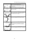
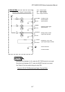
(4) (3)
N.O OUT
R.PUMP
Terminal for starting the auxiliary pump.
The voltage input to the AC. POWER terminal ((19)-(20)) is
output to this terminal through the STP pump rotation. DO
NOT connect the auxiliary pump directly.
Use separate power and a relay.
Use another power and a relay. See Figure 8.2.
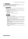
NOTICE
If the I/O TB3 ((1)-(3)) is opened, it is
diagnosed as abnormal auxiliary
pump, the "FAILURE" lamp lights and
the power is cut OFF.
*1
: JIS
8-1