


STP-H600/H1000 Series Instruction Manual
3.3.5 Connecting the Emergency Vent. Valve
The emergency vent. valve stops the STP pump by introducing gases if any
abnormality/error occurs in the STP pump.
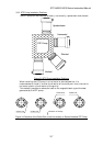
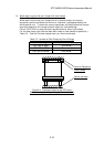
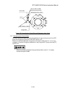
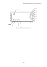
Connect the emergency vent. valve (contained in the attached accessories) to the
purge port as shown in Figure 3.7. Note that the side of the emergency vent. valve
without filter is connected to the purge port.
Connect the cable for the emergency vent. valve to the connector, LEAK VALVE
CON8A, of the STP control unit.
Always attach the emergency vent. valve.
DO NOT close the port of the emergency vent. valve (filter side) with a blank
flange or other type of device.
The allowable gas pressure ranges from zero [atmospheric pressure] to
4.9x10
4
Pa [gauge pressure] (zero [atmospheric pressure] to 0.5kgf/cm
2
[gauge
pressure]).
Use a dry N2 gas or other.
3.3.6 Connecting the Purge Port
When sucking reactive or corrosive gases, introduce a dry N
2
gas or other gas into
the STP pump in order to protect the inside of the STP pump.
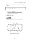
As shown in Figure 3.7, introduce a dry N
2
gas through the electromagnetic vent.
valve, needle valve or similar valve (must be prepared by the customer) from the
purge port.
For instructions on how to introduce the purge gas, See Section 7.1, "Gas Suction."
The proper amount of gas purge is approx. 3.4 10
-2
Pa·m
3
/s (20 SCCM).
The allowable gas pressure ranges from zero [atmospheric pressure] to
4.9x10
4
Pa [gauge pressure] (zero [atmospheric pressure] to 0.5kgf/cm
2
[gauge
pressure]).
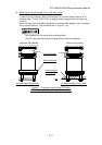
When not introducing the purge gas, close the purge port with the blank flange
(attached at delivery).
3-14