


4 - 13 4 - 13
MELSEC-Q
4 SETUP AND PROCEDURES BEFORE OPERATION
(3) Remedy for insufficient network power supply current capacity
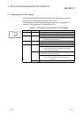
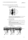
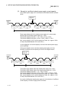
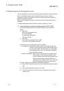
If the network power supply unit is connected to a thick-cable network, as shown
below.
Master station
1.1A
Slave station
1.25A
Slave station
0.5A
120m
Termination
resistance
Termination
resistance
Slave station
0.25A
Slave station
0.25A
Slave station
0.85A
120m
Network power
supply unit
Power supply distance left of the network power supply unit = power supply
distance right of the network power supply unit = 120 m
Total current capacity to the left = 1.1 A + 1.25 A + 0.5 A = 2.85 A
Total current capacity to the right = 0.25 A + 0.25 A + 0.85 A = 1.35 A
Max. current capacity of 120 m of thick cable (from Table 4.4) = approx. 2.56 A
(Linearly interpolated between 100 m and 150 m.)
In this configuration, the current capacity to the left of the network power supply
unit is insufficient.
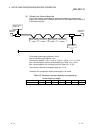
If this type of situation occurs, move the network power supply unit in the
direction of insufficient current capacity (to the left in the diagram above).
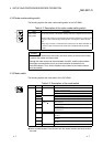
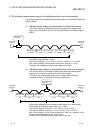
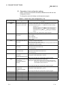
Master station
1.1A
Slave station
1.25A
Slave station
0.5A
100m
Termination
resistance
Termination
resistance
Slave station
0.25A
Slave station
0.25A
Slave station
0.85A
140m
Network power
supply unit
Total power supply distance left of the network power supply unit = 100 m
Total power supply distance right of the network power supply unit = 140 m
Total current capacity to the left = 1.1 A + 1.25 A = 2.35 A
Total current capacity to the right = 0.5 A + 0.25 A + 0.25 A + 0.85 A = 1.85 A
Max. current capacity of 100 m of thick cable (from Table 4.4) = approx. 2.93 A
Max. current capacity of 140 m of thick cable (from Table 4.4) = approx. 2.19 A
(Linearly interpolated between 100 m and 150 m.)
As a result of shifting the network power supply unit in the direction of insufficient
current capacity, it is able to supply power to all nodes.