


4 - 12 4 - 12
MELSEC-Q
4 SETUP AND PROCEDURES BEFORE OPERATION
4.7.2 Calculating network power supply unit installation position and current capacity
This section explains the calculating network power supply unit installation position and
current capacity.
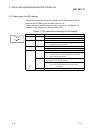
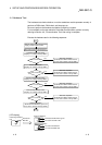
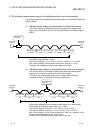
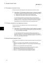
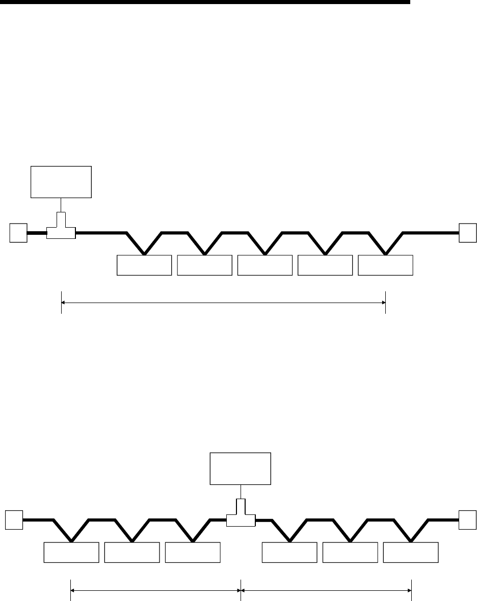
(1) Network power supply unit connected to an end of the network
The current capacity is calculated as shown below when the network power
supply unit is connected to the end of a thick-cable network with a total length of
200 m.
Master station
0.1A
Slave station
0.15A
Slave station
0.05A
Slave station
0.25A
Slave station
0.1A
200m
Termination
resistance
Termination
resistance
Network power
supply unit
Total power supply distance = 200 m
Total current capacity = 0.1 A + 0.15 A + 0.05 A + 0.25 A + 0.1 A = 0.65 A
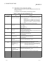
Max. current capacity of 200 m of thick cable (from Table 4.4) = 1.53 A
Therefore, this configuration allows power supply to all nodes.
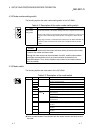
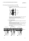
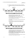
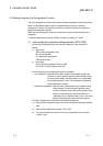
(2) Network power supply unit connected to the center of the network
The current capacity is calculated as shown below when the network power
supply unit it connected at the center of a thick-cable network.
In this case, the network power supply unit can supply twice the current
compared to when it is connected to the end of the network.
Master station
0.1A
Slave station
0.25A
Slave station
0.2A
120m
Termination
resistance
Termination
resistance
Slave station
0.15A
Slave station
0.25A
Slave station
0.15A
120m
Network power
supply unit
Power supply distande left of the network power supply unit = power supply
distance right of the network poewr supply unit = 120 m
Total current capacity to the left = 0.1 A + 0.25 A + 0.2 A = 0.55 A
Total current capacity to the right = 0.15 A + 0.25 A + 0.15 A = 0.55 A
Max. current capacity of 120 m of thick cable (from Table 4.4) = apporox. 2.56 A
(Linearly interpolated between 100 m and 150 m.)
Therefore, this configuration allows power supply to all node.