


3 - 37 3 - 37
MELSEC-Q
3 SPECIFICATIONS
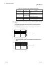
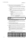
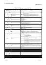
Table 3.22 Parameter setting data (1/2)
Buffer memory address
(hexadecimal)
Item Description
01D4
H
to 01D6
H
Use prohibited —
01D7
H
Constant scan Specifies to make the link scan time constant. (setting range: 0 to 65535 ms (FFFF
H
))
01D8
H
Node number and message group of
the 1st slave node
Lower byte: Node number of the 1st slave node (MAC ID)
00
H
to 3F
H
(0 to 63)
Higher byte: Node that supports 01
H
UCMM and uses message group 3
Node that supports 03
h
UCMM and uses message group 1
Node that does not support 04
H
UCMM (group 2 dedicated server)
80
H
Reserved node
01D9
H
Connection type of the 1st slave node
Selects the connection type of I/O communication.
0001
H
= Polling
0002
H
= Bit strobe
0004
H
= Change-of-state
0008
H
= Cyclic
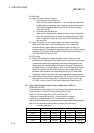
01DA
H
Byte module count of the 1st slave node
Lower byte: Input byte module count
Higher byte: Output byte module count
(For a bit module, eight points are calculated as one byte module, and is set in
hexadecimal. Ex.: 0A
H
for 10 bytes)
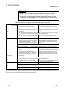
01DB
H
Word module count of the 1st slave
node
Lower byte: Input word module count
Higher byte: Output word module count
(Sets in hexadecimal.)
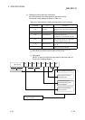
01DC
H
Double-word module count of the 1st
slave node
Lower byte: Input double-word module count
Higher byte: Output double-word module count
(Sets in hexadecimal.)
01DD
H
Expected packet rate of the 1st slave
node
Sets the expected packet rate of the slave node. (Setting range: 0 to 65535 ms
(FFFF
H
))
Setting value = 0000
H
(default value) 200 ms
Setting value
≠
0000
H
Setting value –1 is the expected packet rate (ms)
The setting value varies depending on the connection type. See Table 3.23 for details of
setting values.
01DE
H
Watchdog timeout action of the 1st
slave node
Operation during watchdog timeout at a slave node
Setting value = 0000
H
: (default value)
Same as the following timeout.
Setting value = 0001
H
: Timeout
The connection is placed in timeout state. It will not be recovered until an
operator stops the communication and then resumes it.
Setting value = 0002
H
: Auto Delete
The connection is automatically deleted. At this time the communication
stops once, then resumes automatically. The output is cleared once.
Setting value = 0003
H
: Auto Reset
The communication continues while connection is maintained. The
output is not cleared.
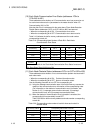
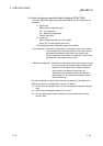
01DF
H
Production inhibit time of the 1st slave
node
Sets the production inhibit time. (Setting range: 0 to 65535 ms (FFFF
H
))
Setting value = 0000
H
: (default value) 10 ms
Setting value
≠
0000
H
Setting value –1 is the minimum transmission interval (ms).
The setting value varies depending on the connection type. See Table 3.23 for details of
setting values.
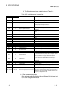
01E0
H
to 01E7
H
2nd node setting Same as the 1st node
01E8
H
to 01EF
H
3rd node setting Same as the 1st node
01F0
H
to 01F7
H
4th node setting Same as the 1st node
01F8
H
to 01FF
H
5th node setting Same as the 1st node
0200
H
to 0207
H
6th node setting Same as the 1st node
0208
H
to 020F
H
7th node setting Same as the 1st node
0210
H
to 0217
H
8th node setting Same as the 1st node
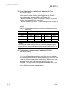
0218
H
to 021F
H
9th node setting Same as the 1st node
0220
H
to 0227
H
10th node setting Same as the 1st node
0228
H
to 022F
H
11th node setting Same as the 1st node
0230
H
to 0237
H
12th node setting Same as the 1st node
0238
H
to 023F
H
13th node setting Same as the 1st node
0240
H
to 0247
H
14th node setting Same as the 1st node
: When setting a value of 32768 or more, set it in hexadecimal.