


3 - 2 3 - 2
MELSEC-Q
3 SPECIFICATIONS
3.2 Functions
This section explains the functions of the QJ71DN91.
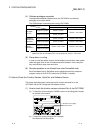
3.2.1 Master function (I/O communication function)
The I/O communication function executes the I/O data communication with each slave
node.
In the I/O communication function, the connection type can be set according to the
specification of the slave node.
There are four connection types: polling, bit strobe, change-of-state, and cyclic. The
connection type can be set with a parameter.
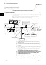
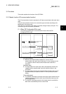
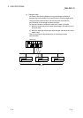
(1) When GX Configurator-DN is used
The following explains the I/O communication function when the GX
Configurator-DN is used.
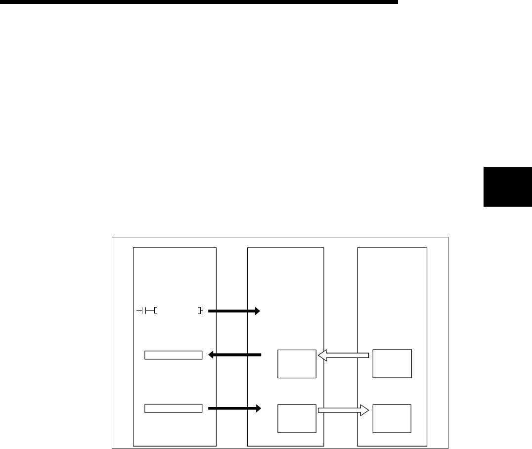
PLC CPU QJ71DN91 Slave node
SET Y11
I/O communication
request
1)
3)
Master function
receive
data area
0700
H
07FF
H
4)
Master function
transmit
data area
0900
H
09FF
H
Transmission
Reception
5)
2)
X
Y
[I/O communication]
1) When the I/O communication request (Y11) is set, the I/O
communication with each slave node starts. It is not necessary to set
Y11, however, when the auto communication start is set with a
parameter.
[Reception data]
2) The input status from each slave node is automatically stored in the
"master function reception data" area of the buffer memory in the
QJ71DN91.
3) The input status stored in the "master function reception data" area of
the buffer memory is loaded onto the PLC CPU by the auto refresh
setting.
[Transmission data]
4) The ON/OFF information to be sent to the slave node is written into the
"master function transmission data" area of the buffer memory by the
auto refresh setting.
5) The ON/OFF information stored in the "master function transmission
data" area is automatically sent to a slave node.
3