


6 - 13 6 - 13
MELSEC-Q
6 UTILITY PACKAGE (GX Configurator-DN)
[Explanation of items]
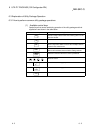
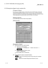
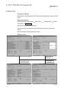
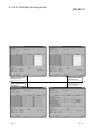
(1) Description of the screen display
Buffer size on module side : Displays the buffer memory size of the setting item.
Number of transfer words
on module side : Displays the number of words to be transferred.
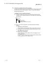
Transfer direction : "
" indicates that data is written from the PLC CPU
to the buffer memory.
"
" indicates that data is read from the buffer
memory to the PLC CPU
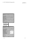
Device on CPU side : Enter the device on the CPU module side to be
automatically refreshed.
The devices that can be used are X, Y, M, L, B, T,
C, ST, D, W, R, and ZR. When using bit device X,
Y, M, L or B, set a number that can be divided by
16 points (examples: X10, Y120, M16, etc.).
In addition, the buffer memory data is stored in 16-
point portions starting from the device number that
was set. For example, if X10 is set, data will be
stored from X10 to X1F.
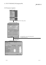
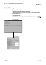
(2) Explanation of command buttons
Make text file
Creates a file containing the screen data in text file format.
End setup
Saves the set data and ends the operation.
Cancel
Cancels the setting and ends the operation.
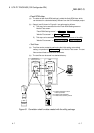
POINT
• The auto refresh settings are stored in the intelligent function module
parameters.
The auto refresh settings become valid by turning the power OFF and then ON
or resetting the CPU module after the intelligent function module parameters
are written to the CPU module.
• The auto refresh settings cannot be changed from the sequence program.
However, processing equivalent to auto refresh can be added using the
FROM/TO instruction of the sequence program.