


7 - 3 7 - 3
MELSEC-Q
7 PROGRAMMING WHEN EXECUTING THE MASTER FUNCTION
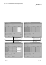
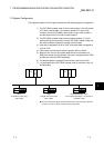
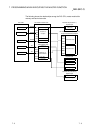
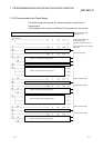
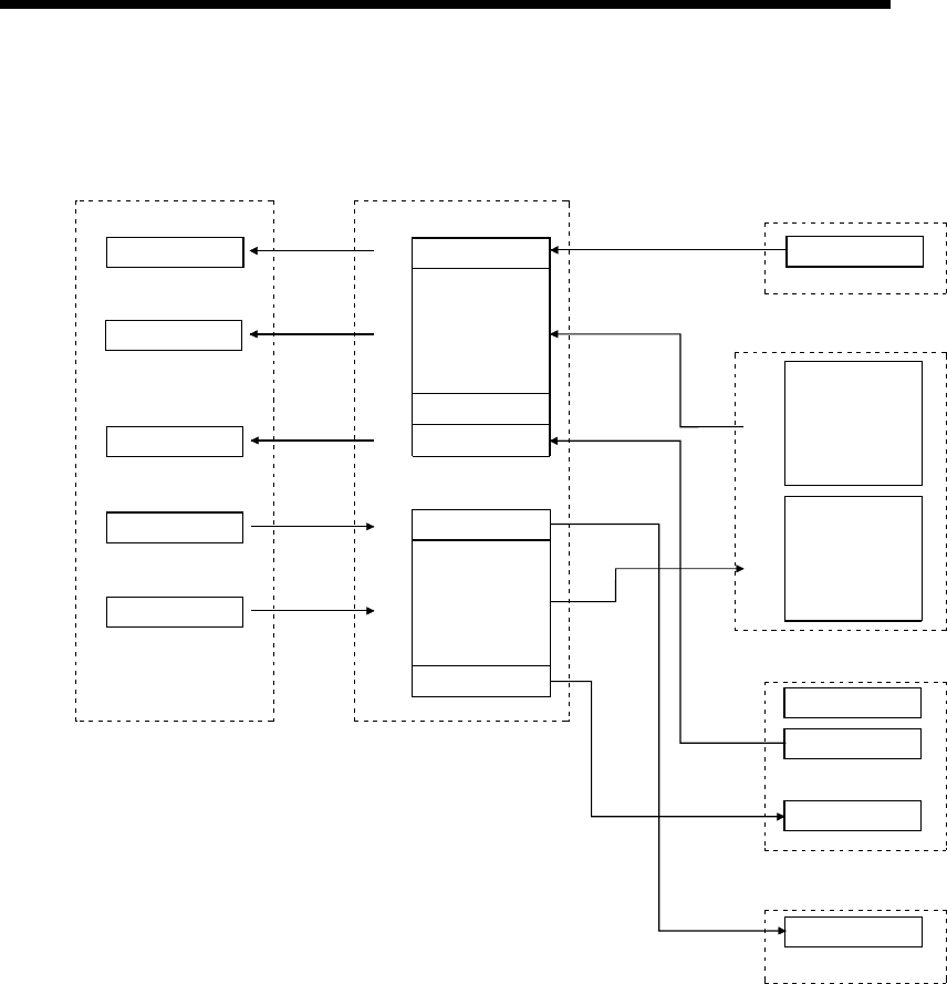
The following shows the relationships among the PLC CPU, master node buffer
memory and each slave node.
PLC CPU QJ71DN91 master node
Remote I/O (Node No. 1)
8-point input
700
H
X100 to X107
Node No. 1 reception
Node No. 4
reception
Node No. 3 status
Node No. 3 reception
701
H
702
H
703
H
704
H
705
H
706
H
X110 to X14F
FROM
FROM
X160 to X16F
FROM
Reception data
900
H
Node No. 2
transmission
Node No. 4
transmission
Node No. 3
transmission
901
H
902
H
903
H
904
H
905
H
Transmission data
Y100 to Y107
TO
Y110 to Y14F
TO
I00 to I07
Input 00 to input 07
Remote I/O (node No. 3)
16-point input
Transmission data
Reception data
Status
I00 to I15
Input 00 to input 15
Dummy output
Remote I/O (node No. 2)
8-point input
QJ71DN91 slave node (node No. 4)
8-byte transmission/reception
O00 to O07
Output 00 to output 07
C00
H
C01
H
C02
H
C03
H
B00
H
B01
H
B02
H
B03
H