


2 - 1 2 - 1
MELSEC-Q
2 SYSTEM CONFIGURATION
2
2 SYSTEM CONFIGURATION
This chapter explains the system configuration of DeviceNet.
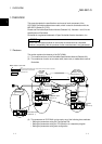
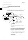
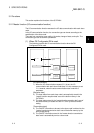
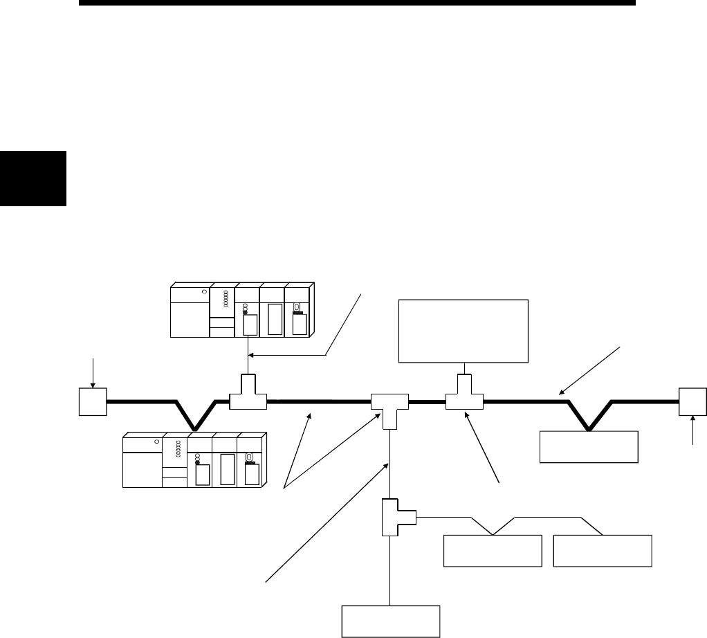
2.1 Overall Configuration
A total of 64 modules including a master node, slave nodes and a master/slave node
can be connected.
Each node is connected via a tap from the trunk line or directly to the trunk line.
The following shows an example of a system configuration:
Terminal resistor
(121
Ω
, 1/4W)
Slave node
Slave node
Slave node Slave node
Terminal resistor
(121
Ω
, 1/4W)
Network power-supply
module (24V DC)
Tap
Drop line (branch line)
Power supply tap
Drop line
Trunk line (main line)
Master node
Slave node
1) The QJ71DN91 can be used as a master node, a slave node or a
master/slave node.
2) A combined maximum of 64 master node and slave nodes can be
connected.
3) There is no need to connect the master node and slave nodes in the
order of node number.
4) The network cable consists of trunk line (main line) and drop lines
(branch lines).
Terminal resistors are required on both sides of the trunk line.
5) It is necessary to connect the network power supply in order to supply
the power supply to the communication circuit in addition to the
operating power supply of each node.
6) Use the terminal resistors included in the package, or they must be
furnished by the user.