


Index - 1 Index - 1
Ind.
INDEX
[A]
Auto configuration completion ...................... 3-23
Auto communication start setting.................. 3-46
Auto configuration executing......................... 3-23
Auto configuration operation setting ............. 3-40
Auto configuration request............................ 3-23
[B]
Bit strobe.......................................................... 3-5
Buffer memory list ......................................... 3-24
Bus error counter........................................... 3-33
Bus off counter .............................................. 3-33
[C]
Change of state............................................... 3-6
Checking the LEDs ......................................... 9-2
Communication error codes............................ 9-6
Communication with a specific slave node cannot
be performed ................................................... 9-4
Communication with all slave nodes cannot be
performed ........................................................ 9-3
Communication with the master node cannot be
performed ........................................................ 9-5
Cyclic .............................................................. 3-7
[D]
DeviceNet general error code list ................. 3-31
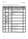
Differences between the QJ71DN91 and the
AJ71DN91/A1SJ71DN91............................App-2
Down node detection disable status............. 3-36
[E]
Each node communication error status........ 3-35
Each node communication status................. 3-34
Each node configuration status .................... 3-33
Each node obstacle status............................ 3-35
EDS file .......................................................App-6
Error codes ...................................................... 9-6
Execution error cords of message
communication ................................................ 9-9
Expected packet rate .................................... 3-39
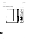
External dimension diagram .......................App-1
[F]
Function version...............................................2-4
[G]
GX Configurator-DN ................................ 2-4, 6-1
GX Developer ..................................................2-4
[H]
H/W test completion.......................................3-22
H/W test error detection.................................3-22
H/W testing.....................................................3-22
H/W test item display area.............................3-45
H/W test result storing area...........................3-45
[I]
I/O communicating.........................................3-14
I/O communication request............................3-14
I/O communication with the master node .......8-3
I/O communication with the slave nodes ........7-7
I/O signal list...................................................3-13
[L]
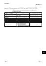
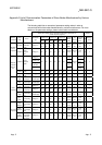
List of communication parameters of slave nodes
manufactured by various manufacturers ... App-5
[M]
Master function (I/O communication function) 3-2
Master function communication status..........3-32
Master function for IO address area..............3-41
Master function for error Information.............3-33
Master function for error set signal................3-18
Master function for error reset request..........3-18
Master function receive data .........................3-47
Master function transmit data ........................3-48
Maximum link scan time ................................3-41
Message communication command .............3-26
Message communication completion............3-17
Message communication data.......................3-29
Message communication error signal ...........3-17
Message communication function...................3-8
Message communication request .................3-17
Message communication result.....................3-28
Minimum link scan time .................................3-41
Mode switch number......................................3-44