


7 - 11 7 - 11
MELSEC-Q
7 PROGRAMMING WHEN EXECUTING THE MASTER FUNCTION
7.7 Allocating Transmission/Reception Data Storage Devices for Future Expansion
If the transmission/reception data of each slave node varies depending on the system,
it is necessary to change the sequence program when the transmission/reception data
length changes. However, this can be avoided by allocating a transmission/reception
data storage device for each node, using the I/O address area information for the
master function in the buffer memory, and executing the FROM and TO instructions.
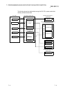
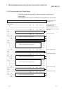
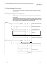
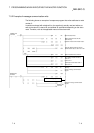
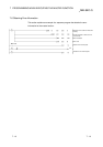
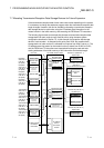
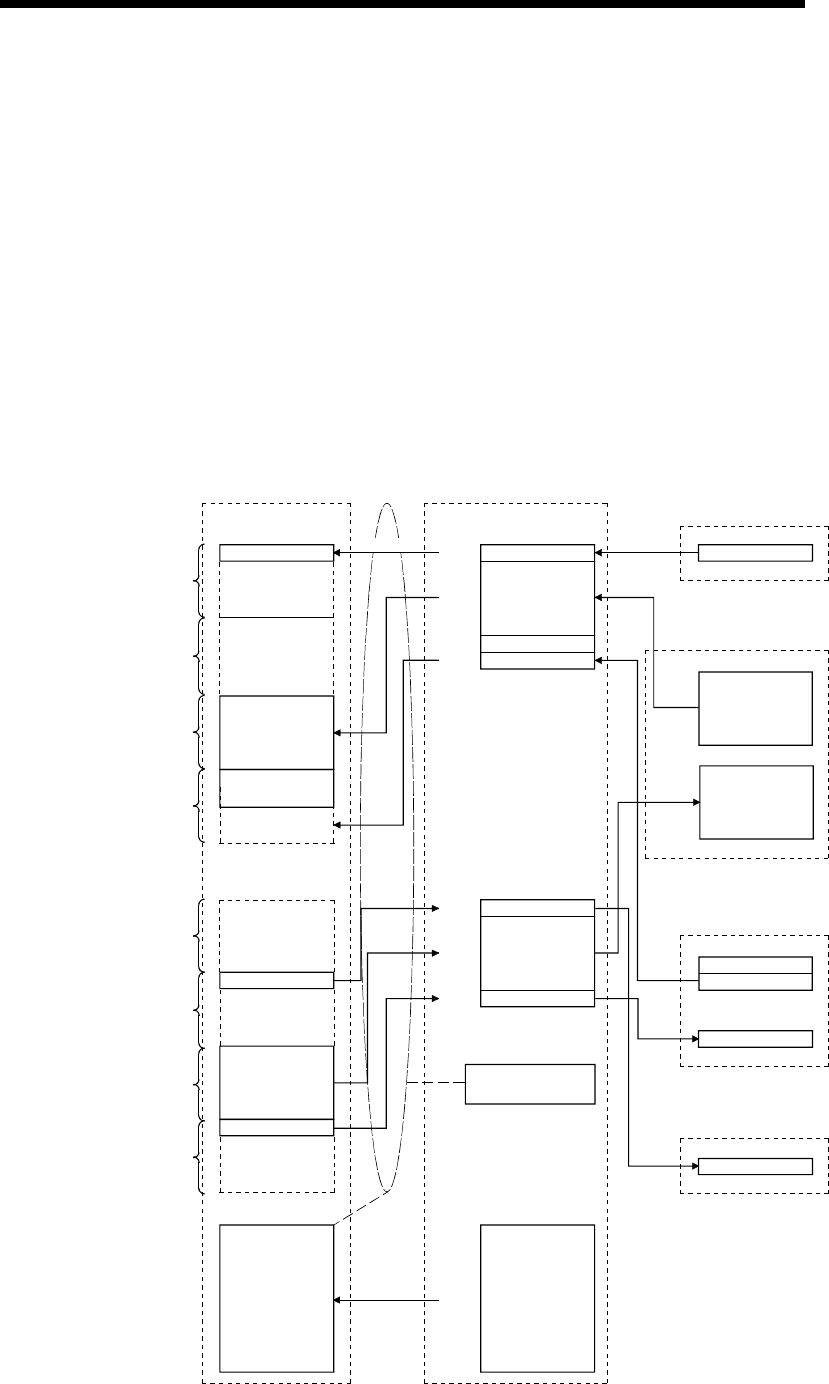
The following figure shows an example that allocates a transmission/reception data
storage device for each node at every fixed 64 points, using the same system
configuration described in Section 7.2. In this example, the reception data storage
device of node number 1 is allocated for 64 points from X200, the reception data
storage device of node number 2 is allocated for 64 points from X240, and so on. The
I/O address area information for the master function is stored from D1000 to D1251,
and the FROM and TO instructions are executed while using the read and write
starting addresses of the buffer memory of this information and the data length.
PLC CPU
Reception
data area of
node No. 1
(64 points)
Transmission
data area of
node No. 1
(64 points)
X200 to X207
X208 to X23F
(For future
expansion)
X240 to X27F
(For future
expansion)
X2E0 to X2FF
(For future expansion)
X280 to X2BF
X2C0 to X2DF
Y200 to X23F
(For future
expansion)
Y240 to X247
Y248 to X27F
(For future
expansion)
Y2D0 to X2FF
(For future
expansion)
Y280 to X2BF
Y2C0 to X2CF
D1000 to D1251
I/O address
information
700H
701H
702H
703H
704H
705H
706H
900H
901H
902H
903H
904H
500H
5FBH
I/O address
area for
the master
function
to
Executes based on the
information from
D1000 to D1251.
902H
Node No. 2 transmission
Node No. 4
transmission
Node No. 3 transmission
Transmission data
Node No. 1 reception
Reception data
Station No. 4
reception
Node No. 3 reception
Node No. 3 status
Remote I/O (station No. 1)
8-point input
QJ71DN91 master station
Reception data
Transmission
data
Input 00 to input 07
I00 to I07
QJ71DN91 slave station
(node No. 4)
8-byte transmission/reception
C00H
C01H
C02H
C03H
B00H
B01H
B02H
B03H
Remote I/O (node No. 3)
16-point input
Input 00 to input 15
Output 00 to output 07
I00 to I15
O00 to O07
Dummy output
Status
FROM
TO
FROM
FROM
FROM
TO
TO
Reception
data area of
node No. 2
(64 points)
Reception
data area of
node No. 4
(64 points)
Reception
data area of
node No. 3
(64 points)
Transmission
data area of
node No. 2
(64 points)
Transmission
data area of
node No. 4
(64 points)
Transmission
data area of
node No. 3
(64 points)
Remote I/O (node No. 2)
8-point input