


3 - 13 3 - 13
MELSEC-Q
3 SPECIFICATIONS
3.3 I/O Signals for the PLC CPU
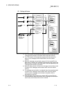
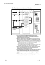
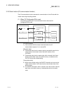
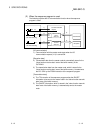
This section explains the input/output signals for the PLC CPU of the QJ71DN91.
3.3.1 I/O signal list
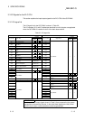
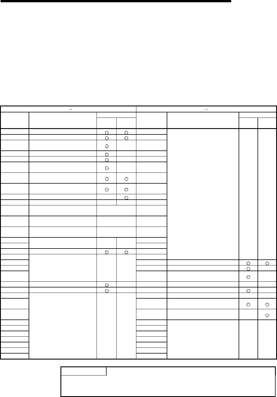
The I/O signal list for the QJ71DN91 is shown in Table 3.2.
The I/O numbers (X/Y) and I/O addresses described from this chapter are applicable
when the QJ71DN91 is installed in slot 0 of the basic base module.
Table 3.2 I/O signal list
QJ71DN91 PLC CPU PLC CPU QJ71DN91
Usability Usability
Input number Signal name
Master
function
Slave
function
Output number Signal name
Master
function
Slave
function
X00 Watchdog Timer Error Y00
X01 I/O Communicating Y01
X02
Message Communication
Completion
—Y02
X03 Master Function For Error Set Signal —Y03
X04 Slave Down Signal —Y04
X05
Message Communication Error
Signal
—Y05
X06
Saving Parameter To The Flash
ROM
Y06
X07
Save Parameter To Flash ROM
Completion
Y07
X08 Slave Function For Error Set Signal — Y08
X09 Use prohibited — — Y09
X0A H/W Testing
At the time of the
hardware test
Y0A
X0B H/W Test Completion
At the time of the
hardware test
Y0B
X0C H/W Test Error Detection
At the time of the
hardware test
Y0C
X0D Y0D
X0E
Use prohibited — —
Y0E
X0F Module Ready Y0F
X10 Y10
Use prohibited — —
X11 Y11 I/O Communication Request
X12 Y12 Message Communication Request —
X13
Use prohibited — —
Y13
Master Function For Error Reset
Request
—
X14 Auto Configuration Executing — Y14 Use prohibited — —
X15 Auto Configuration Completion — Y15 Auto Configuration Request —
X16 Y16 Use prohibited — —
X17 Y17
Save Parameter To Flash ROM
Request
X18 Y18
Slave Function For Error Reset
Request
—
X19 Y19
X1A Y1A
X1B Y1B
X1C Y1C
X1D Y1D
X1E Y1E
X1F
Use prohibited — —
Y1F
Use prohibited — —
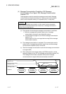
IMPORTANT
The use-prohibited output signals shown in Table 3.2 are accessed by the system
and cannot be accessed by the user. In the event these signals are used (turned
ON/OFF) by the user, normal operations cannot be guaranteed.