


3 - 24 3 - 24
MELSEC-Q
3 SPECIFICATIONS
3.4 Buffer Memory
The buffer memory transfers data between the QJ71DN91 and the PLC CPU.
The FROM and TO instructions of the PLC CPU are used to read and write the buffer
memory data in the QJ71DN91.
The contents of the buffer memory are reset to 0 when the power is turned OFF or
when the PLC CPU is reset.
However, the "parameter" area is initialized using the saved parameters if the
parameters have been saved in the flash ROM.
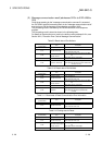
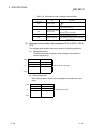
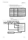
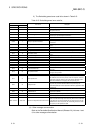
3.4.1 Buffer memory list
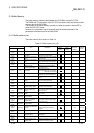
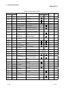
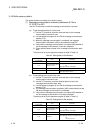
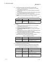
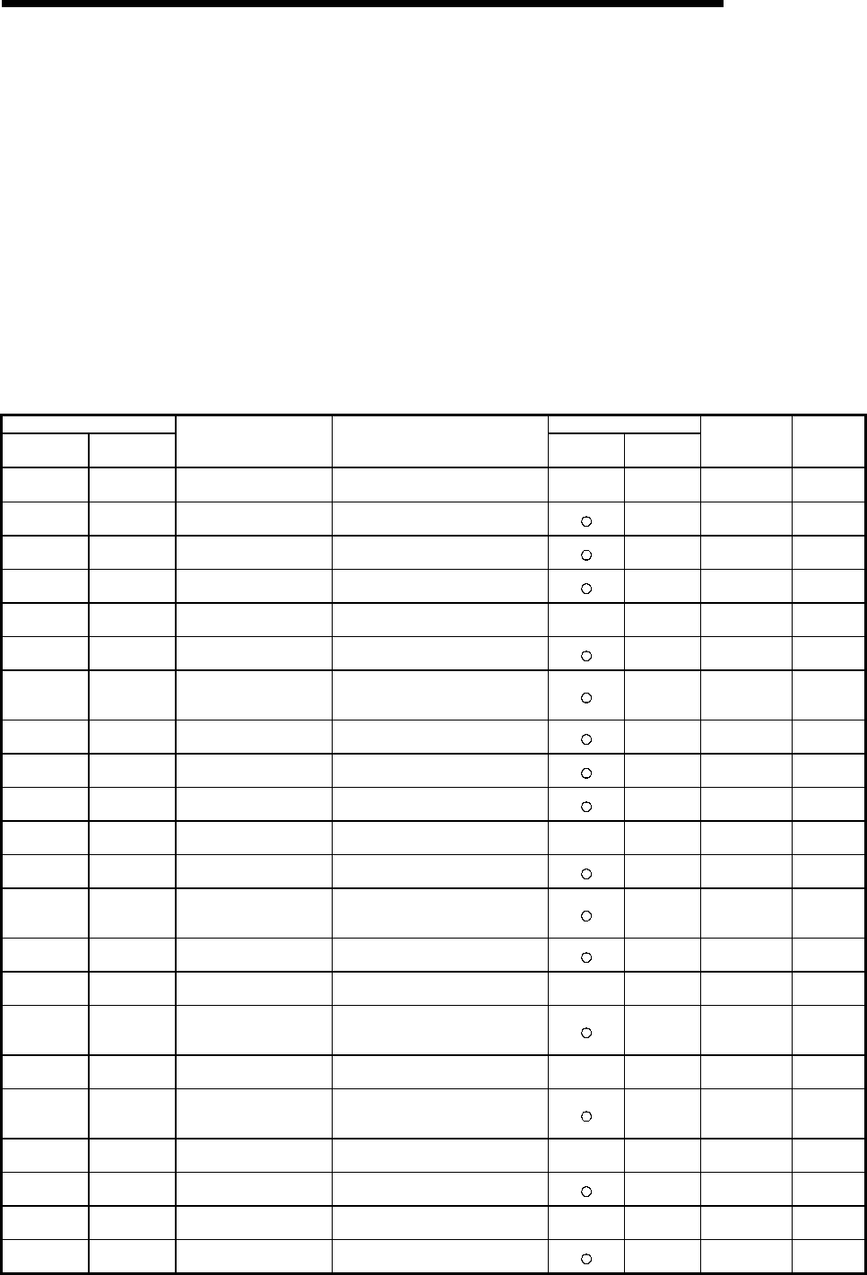
The buffer memory list is shown in Table 3.3.
Table 3.3 Buffer memory list (1/2)
Address Usability
Hexadecimal Decimal
Item Description
Master
function
Slave
function
Write from the
PLC CPU
allowed?
Reference
section
0000
H
to
010F
H
256 to 271 Use prohibited — — — — —
0110
H
to
011F
H
272 to 287
Message communication
command
Stores the request data for executing
the message communication.
— Yes 3.4.2 (1)
0120
H
to
012F
H
288 to 303
Message communication
result
Stores the result data of the message
communication.
— No 3.4.2 (2)
0130
H
to
01A7
H
304 to 423
Message communication
data
Stores the transmission and reception
data of the message communication.
— Yes 3.4.2 (3)
01A8
H
to
01AF
H
424 to 431 Use prohibited — — — — —
01B0
H
432
Master Function
Communication Status
Stores the communication status of
the master function.
— No 3.4.2 (4)
01B1
H
433
Master Function For Error
Information
Higher byte: Error code
Lower byte: Stores the node number
where the error occurred.
— No 3.4.2 (5)
01B2
H
434 Bus Error Counter
Stores the number of times errors are
detected in the communication data.
— No 3.4.2 (6)
01B3
H
435 Bus Off Counter
Stores the number of communication
errors.
— No 3.4.2 (7)
01B4
H
to
01B7
H
436 to 439
Each Node Configuration
Status
Indicates whether or not each slave
node is set with a parameter.
— No 3.4.2 (8)
01B8
H
to
01BB
H
440 to 443 Use prohibited — — — — —
01BC
H
to
01BF
H
444 to 447
Each Node
Communication Status
Indicates whether or not each node is
executing I/O communication.
— No 3.4.2 (9)
01C0
H
to
01C3
H
448 to 451
Each Node
Communication Error
Status
Indicates whether an I/O
communication error has occurred or
not in each node.
— No 3.4.2 (10)
01C4
H
to
01C7
H
452 to 455
Each Node Obstacle
Status
Indicates whether or not each node
has a trouble.
— No 3.4.2 (11)
01C8
H
to
01CB
H
456 to 459 Use prohibited — — — — —
01CC
H
to
01CF
H
460 to 463
Down Node Detection
Disable Status
Sets whether or not the "slave down"
signal (X04) reflects the down status
of each slave node.
— No 3.4.2 (12)
01D0
H
to
01D3
H
464 to 467 Use prohibited — — — — —
01D4
H
to
03CF
H
468 to 975
Parameters for the master
function
Area for setting parameters for the
master function by the sequence
program.
— Yes 3.4.2 (13)
03D0
H
to
03EF
H
976 to 1007 Use prohibited — — — — —
03F0
H
1008
Auto configuration
operation setting
Sets up the operation of the auto
configuration.
— Yes 3.4.2 (14)
03F1
H
to
04FF
H
1009 to 1279 Use prohibited — — — — —
0500
H
to
05FB
H
1280 to 1531
Master Function For I/O
Address Area
Displays the address and size of each
I/O data for the master function.
— No 3.4.2 (15)