


3 - 33 3 - 33
MELSEC-Q
3 SPECIFICATIONS
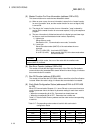
(5) Master Function For Error Information (address 01B1
H
/433)
The communication error code that was detected is stored.
(a) When an error occurs, the error information is stored in the "master function
for error information" area, and the master function for error set signal (X03)
is turned ON.
(b) The data in the " master function for error information " area is cleared by
turning ON the master function for error reset request (Y13) by the sequence
program.
(c) The error information is divided and stored in the higher byte and lower byte
for the error code and the detected node number, respectively.
1) Higher byte
Stores the error code.
See Section 9.2.1, "Communication error code," for details.
2) Lower byte
Stores the node number (MAC ID) of the node where the error
occurred.
FE
H
, FF
H
(254, 255): Local node (QJ71DN91)
0
H
to 3F
H
(0 to 63): Node number (MAC ID) of the slave node where
the error occurred.
POINT
If errors occur at multiple nodes, the error of the node with the smallest node
number (MAC ID) is stored.
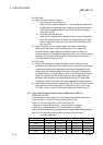
(6) Bus Error Counter (address 01B2
H
/434)
The number of times that the illegal frame count of the CAN chip (DeviceNet's
communication chip) exceeded 96 is stored. When this value is large, it indicates
that communication is unstable.
(7) Bus Off Counter (address 01B3
H
/435)
The number of times that the QJ71DN91 makes a transition to the Bus-off status
is stored. When this value is large, it indicates that communication is unstable.
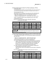
(8) Each Node Configuration Status (addresses 01B4
H
to 01B7
H
/436
to 439)
When I/O Communication Request (Y11) turns ON and no errors are found as a
result of parameter check, the status of parameter setting for each slave node is
stored.
• When the corresponding bit is ON: Parameter has already been set.
• When the corresponding bit is OFF: Parameter has not been set.
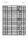
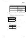
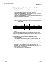
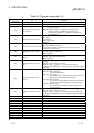
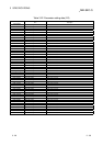
Table 3.17 lists the buffer memory address and the node number corresponding
to each bit.
Table 3.17 Corresponding node number of each bit with each node in
configuration status
Buffer memory address Corresponding node number of each bit
(hexadecimal) Bit 15 Bit 14
…
Bit 1 Bit 0
01B4
H
Node 15 Node 14
…
Node 1 Node 0
01B5
H
Node 31 Node 30
…
Node 17 Node 16
01B6
H
Node 47 Node 46
…
Node 33 Node 32
01B7
H
Node 63 Node 62
…
Node 49 Node 48