


3 - 36 3 - 36
MELSEC-Q
3 SPECIFICATIONS
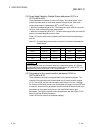
(12) Down Node Detection Disable Status (addresses 01CC
H
to
01CF
H
/460 to 463)
These addresses set whether or not the I/O signal, "slave down signal" (X04),
reflects the down status of each slave node as indicated by the "each node
communication status" (addresses 01BC
H
to 01BF
H
/444 to 447).
• When the corresponding bit is ON: The slave down signal (X04) is not turned
ON even if the corresponding slave node is down.
• When the corresponding bit is OFF: The slave down signal (X04) is turned ON
when the corresponding slave node is down.
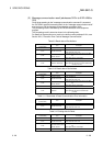
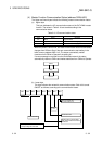
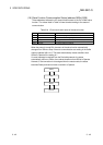
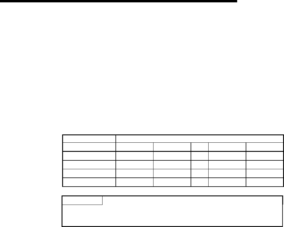
Table 3.21 lists the buffer memory address and node number corresponding to
each bit.
Table 3.21 Corresponding node number of each bit for the down node detection
disable status
Buffer memory address Corresponding node number of each bit
(hexadecimal) Bit 15 Bit 14
…
Bit 1 Bit 0
01CC
H
Node 15 Node 14
…
Node 1 Node 0
01CD
H
Node 31 Node 30
…
Node 17 Node 16
01CE
H
Node 47 Node 46
…
Node 33 Node 32
01CF
H
Node 63 Node 62
…
Node 49 Node 48
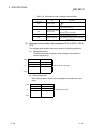
POINT
For the node that is set as a reserved node by the parameter setting, turn ON the
corresponding bit of the down node detection disable status. If it remains OFF, it is
recognized as a down node even if it is a reserved node.
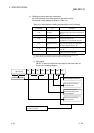
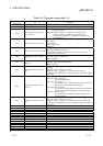
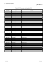
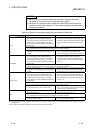
(13) Parameters for the master function (addresses 01D4
H
to
03CF
H
/468 to 975)
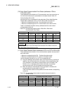
These addresses are used to set parameters by the sequence program. The
contents of the parameters are checked when the I/O communication request
(Y11) is turned ON, and the communication starts if there is no error. Although
the contents of the buffer memory are cleared when the power is turned OFF and
at reset, the contents of the parameters saved in the flash ROM are stored in the
parameters for the master function area if the flash ROM contains valid
parameters. Turn ON the request to save parameters to the flash ROM (Y17) to
save it in the flash ROM as necessary.
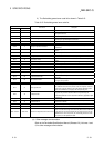
Table 3.22 lists the contents of parameter settings.