


4 - 4 4 - 4
MELSEC-Q
4 SETUP AND PROCEDURES BEFORE OPERATION
4.2 Loading and Installation
The following section explains the precautions when handling the QJ71DN91 from the
time they are unpacked until they are installed.
For more details on the loading and installation of the module, refer to the User's
Manual for the PLC CPU used.
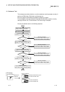
4.2.1 Handling precautions
(1) Do not drop the module casing or connector, or do not subject it to strong impact.
(2) Do not remove the printed-circuit board of each module from its case. This may
cause a failure in the module.
(3) Be careful not to let foreign objects such as wire chips get inside the module.
These may cause fire, breakdown or malfunction.
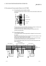
(4) The top surface of the module is covered with a protective film to prevent foreign
objects such as wire chips from entering the module during wiring. Do not
remove this film until the wiring is complete.
Before operating the system, be sure to remove the film to provide adequate heat
ventilation.
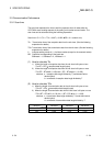
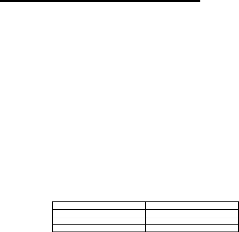
(5) Tighten the mounting screws using the torque within the range listed below. If the
screws are not tightened securely, it may cause short-circuit, breakdown or
malfunction.
Screw location Clamping torque range
Module mounting screws (M3 screws) 36 to 48 N•cm
DeviceNet connector mounting screws 35.3 to 48.0 N•cm
DeviceNet connector wiring mounting screws 60.8 to 82.3 N•cm
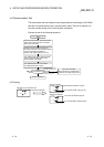
(6) To mount the module on the base unit, securely insert the module mounting
latches into the mounting holes on the base unit. Improper installation may result
in a malfunction or breakdown of the module, or may cause the module to fall off.
4.2.2 Installation environment
For more details on the installation environment, refer to the User's Manual for the PLC
CPU module used.