


3 - 47 3 - 47
MELSEC-Q
3 SPECIFICATIONS
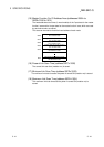
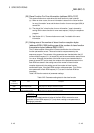
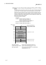
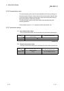
(29) Master Function Receive Data (addresses 0700
H
to 07FF
H
/1792 to
2047)
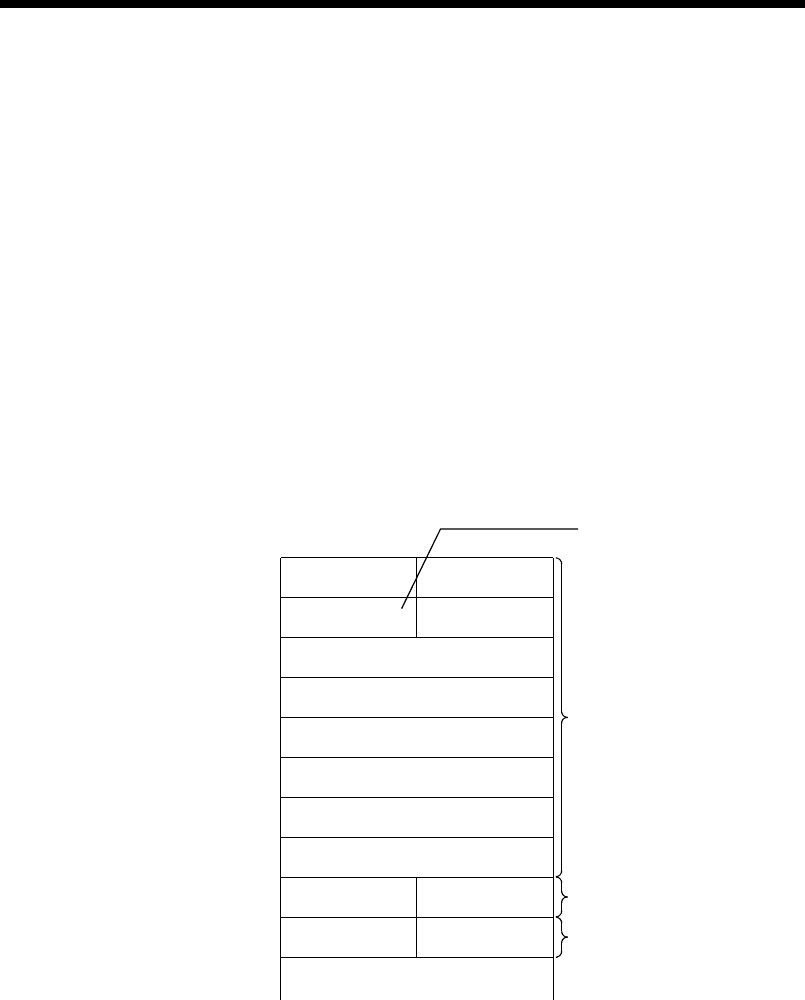
The data that was received from each slave node is stored. The data assignment
is shown below. The data is stored in the word boundaries of the slave nodes.
Double-word data is stored in the order of lower word first and higher word next.
If there is an odd number of byte input modules, one byte of empty area will be
inserted for alignment at the word boundary. Bit input modules are treated in the
same way as the byte input modules.
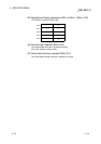
The following shows an example:
<Example>
1st node - Number of byte input modules = 3
Number of word input modules = 3
Number of double-word input modules = 2
2nd node - Number of byte input modules = 1
3rd node - Number of byte input modules = 1
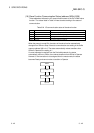
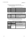
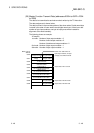
Buffer memory
address
0700
H
0701
H
0702
H
0703
H
0704
H
0705
H
0706
H
0707
H
0708
H
0709
H
If there in an odd number of
byte input modules, one byte
of empty area will be inserted.
Input data of the 1st node
Input data of the 3rd node
2nd byte module 1st byte module
3rd byte module
Empty
1st word module
2nd word module
Lower word of the
1st double-word module
Higher word of
the 1st double-word module
Lower word of
the 2nd double-word module
Higher word of
the 2nd double-word module
1st byte module
1st byte module
Input data of the 2nd node
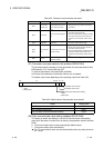
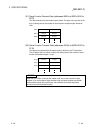
Word input module: Numeric data represented by bit 9 to 16
Double-word input module: Numeric data represented by bit 17 to 32
Byte input module: Data represented by ON/OFF, or numeric data
represented by bit 1 to 8