


3 - 39 3 - 39
MELSEC-Q
3 SPECIFICATIONS
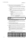
POINT
(1) Write "0" in the unnecessary parameter area when creating a parameter.
Otherwise, an error may occur if the previous data remains.
(2) Because of the limited number of writes of the flash ROM, execute the save
parameter to flash ROM request (Y17) only when creating a new parameter or
changing a parameter.
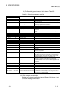
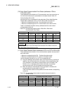
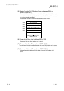
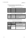
Table 3.23 Details of the expected packet rate and production inhibit time
Expected packet rate Production inhibit time
(1) Sets the communication watchdog timer value for the
slave node. When the communication between the
master node and the slave node stops for the duration
represented by “value of this setting
4,” the slave
node executes the operation specified by the Watchdog
Timeout Action.
(1) Minimum transmission interval of the slave node = Sets
the minimum time that the slave node can prepare the
transmission data. The master node transmits the polling
request to the slave node at this time interval or longer.
1
(2) When the value of the expected packet rate setting is not equal to 1, i.e., when the expected packet rate is not equal to 0
ms, the expected packet rate must be equal to or greater than the production inhibit time.
Polling
(3) When the value of this setting = 1, i.e., when the expected
packet rate = 0 ms, the watchdog timer monitor function
is invalid.
(3) When the set value = 1, i.e. when the production inhibit
time = 0 ms, the master node transmits the polling
request to the slave node at intervals of the module scan.
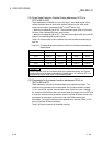
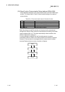
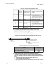
(1) Sets the communication watchdog timer value of the
slave node. When the communication between the
master node and the slave node stops for the duration
represented by “value of this setting
4,” the slave
node executes the operation specified by the Watchdog
Timeout Action.
(1) Minimum transmission interval of the slave node = Sets
the minimum time that the slave can prepare the
transmission data. The master node transmits the bit
strobe request to the slave node at this time interval or
longer.
1
(2) When the value of the expected packet rate setting is not equal to 1, i.e., when the expected packet rate is not equal to
0ms, the expected packet rate must be equal to or greater than the production inhibit time.
Bit strobe 2
(3) When the value of this setting = 1, i.e., when the expected
packet rate = 0 ms, the watchdog timer monitor function
is invalid.
(3) When the set value = 1, i.e. when the production inhibit
time = 0 ms, the master node transmits the bit strobe
request to the slave node at intervals of the module scan.
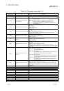
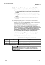
(1) Sets the communication watchdog timer value for the
slave node. When the communication between the
master node and the slave node stops for the duration
represented by “value of this setting
4,” the slave
node executes the operation specified by the Watchdog
Timeout Action.
(1) Set the minimum time when the slave node can receive
data. The master node transmits the output data to the
slave node at this time interval. (The master node also
transmits data to the slave node when the output data
changes.)
1
(2) When the value of the expected packet rate setting is not equal to 1, i.e., when the expected packet rate is not equal to 0
ms, the expected packet rate must be equal to or greater than the production inhibit time.
Change-of-state
(3) When the set value = 1, i.e. the expected packet rate = 0
ms, the watchdog timer monitor function is invalid.
(3) When the set value = 1, i.e. when the production inhibit
time = 0 ms, the master node transmits data to the slave
node only when the output data changes.
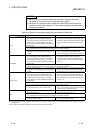
(1) Specifies the interval of data transmissions from the slave
node to the master node.
(1) Specifies the interval of data transmissions from the
master node to the slave node.
1
(2) When the value of the expected packet rate setting is not equal to 1, i.e., when the expected packet rate is not equal to 0
ms, the expected packet rate must be equal to or greater than the production inhibit time.
Cyclic
(3) When the setting value = 1, i.e., the expected packet rate
= 0 ms, the setting is inhibited.
(3) When the setting value = 1, i.e., the production inhibit
time = 0 ms, the setting is inhibited.
1: If the setting of the production inhibit time is shorter than the scan time of the module, the master node transmits data to the slave node at the intervals of
the module scan.
2: The setting of the production inhibit time must be the same in all bit strobe connections.