


4 - 11 4 - 11
MELSEC-Q
4 SETUP AND PROCEDURES BEFORE OPERATION
4.7 Instructions for Connecting the Network Power Supply
This section explains the instructions for connecting the network power supply.
4.7.1 Network power supply unit installation position
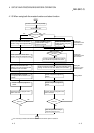
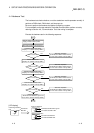
Follow the procedure below to determine the position to install the network power
supply unit.
1) Calculate the current consumption of the nodes required on the network.
2) Measure the total length of the network.
3) Refer to Tables 4.4 and 4.5 to determine the maximum current capacity
corresponding to the network length and type of cable used.
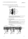
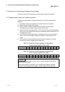
4) If the current value calculated at step 1) is less than the current value calculated at
step 3), any of the network power supply unit installation positions explained in the
next page can be used.
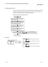
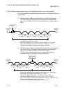
5) If the current value calculated at step 1) exceeds the current value calculated at
step 3), refer to the next page to determine whether the network power to all
nodes.
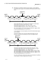
6) If the results from step 5) indicate that power cannot be supplied to all nodes,
increase the number of network power supply units.
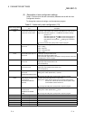
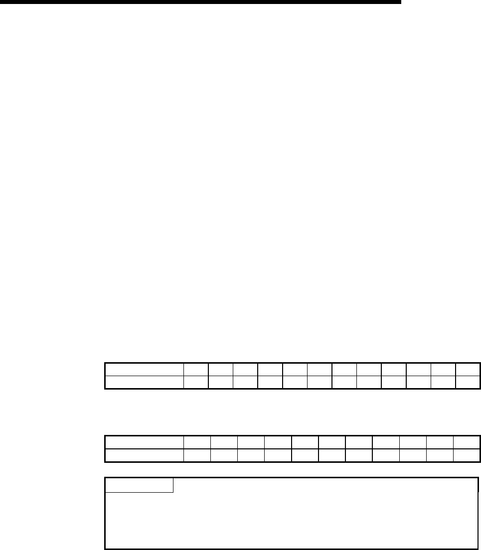
Table 4.4 Maximum current capacity corresponding
to the network length of thick cable
Network length (m) 0 25 50 100 150 200 250 300 350 400 450 500
Maximum current (A) 8.00 8.00 5.42 2.93 2.01 1.53 1.23 1.03 0.89 0.78 0.69 0.63
Table 4.5 Maximum current capacity corresponding
to the network length of thin cable
Network length (m) 0 10 20 30 40 50 60 70 80 90 100
Maximum current (A) 3.00 3.00 3.00 2.06 1.57 1.26 1.06 0.91 0.80 0.71 0.64
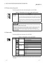
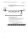
POINT
Use a network power supply unit with a current capacity exceeding the required
total current consumption.
If the current capacity is insufficient, use of multiple power supplies is possible.
However, if using multiple power supplies, a power supply tap should be used.