


2 - 3 2 - 3
MELSEC-Q
2 SYSTEM CONFIGURATION
2.2 Applicable Systems
This section describes the system configuration for the QJ71DN91.
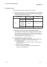
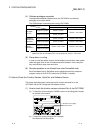
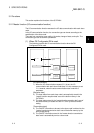
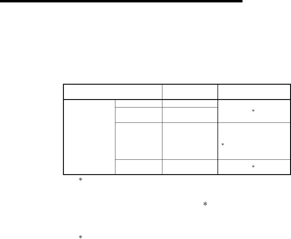
(1) Applicable module and the number of modules that can be installed
The following are the CPU module in which the QJ71DN91 can be installed and
the number of modules that can be installed.
Applicable module
Number of modules that
can be installed
Remarks
Q00JCPU Maximum 16
Q00CPU
Q01CPU
Maximum 24
(
1
)
Q02CPU
Q02HCPU
Q06HCPU
Q12HCPU
Q25HCPU
Maximum 64
Can be installed in Q mode only
(
1
)
CPU module
Q12PHCPU
Q25PHCPU
Maximum 64
(
1
)
1 See User's Manual (Function Explanation, Program Fundamentals) for the CPU module to use.
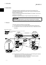
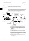
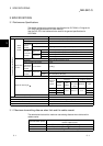
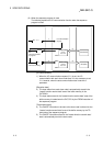
(2) Base unit in which the conversion module can be installed
The QJ71DN91 can be installed in any I/O slot ( 2) of the base unit. However, a
power shortage may occur depending on the combination with other installed
modules and the number of modules used, so always take into consideration the
power supply capacity when installing modules.
2 Limited to the range of the number of I/O points in the CPU module.
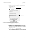
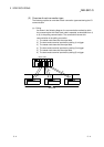
(3) Compatibility with a multiple PLC system
First read the QCPU (Q mode) (Function Explanation, Program Fundamentals)
User's Manual if the QJ71DN91 is used with a multiple PLC system.
(a) Compatible QJ71DN91
Use a QJ71DN91 with function version B or higher if using the module in a
multiple PLC system.
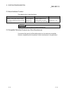
(b) Intelligent function module parameters
Perform PLC write of the intelligent function module parameters to the
control PLC of the QJ71DN91 only.