


7 - 2 7 - 2
MELSEC-Q
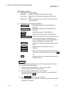
7 PROGRAMMING WHEN EXECUTING THE MASTER FUNCTION
7
7.2 System Configuration
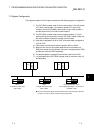
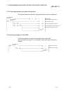
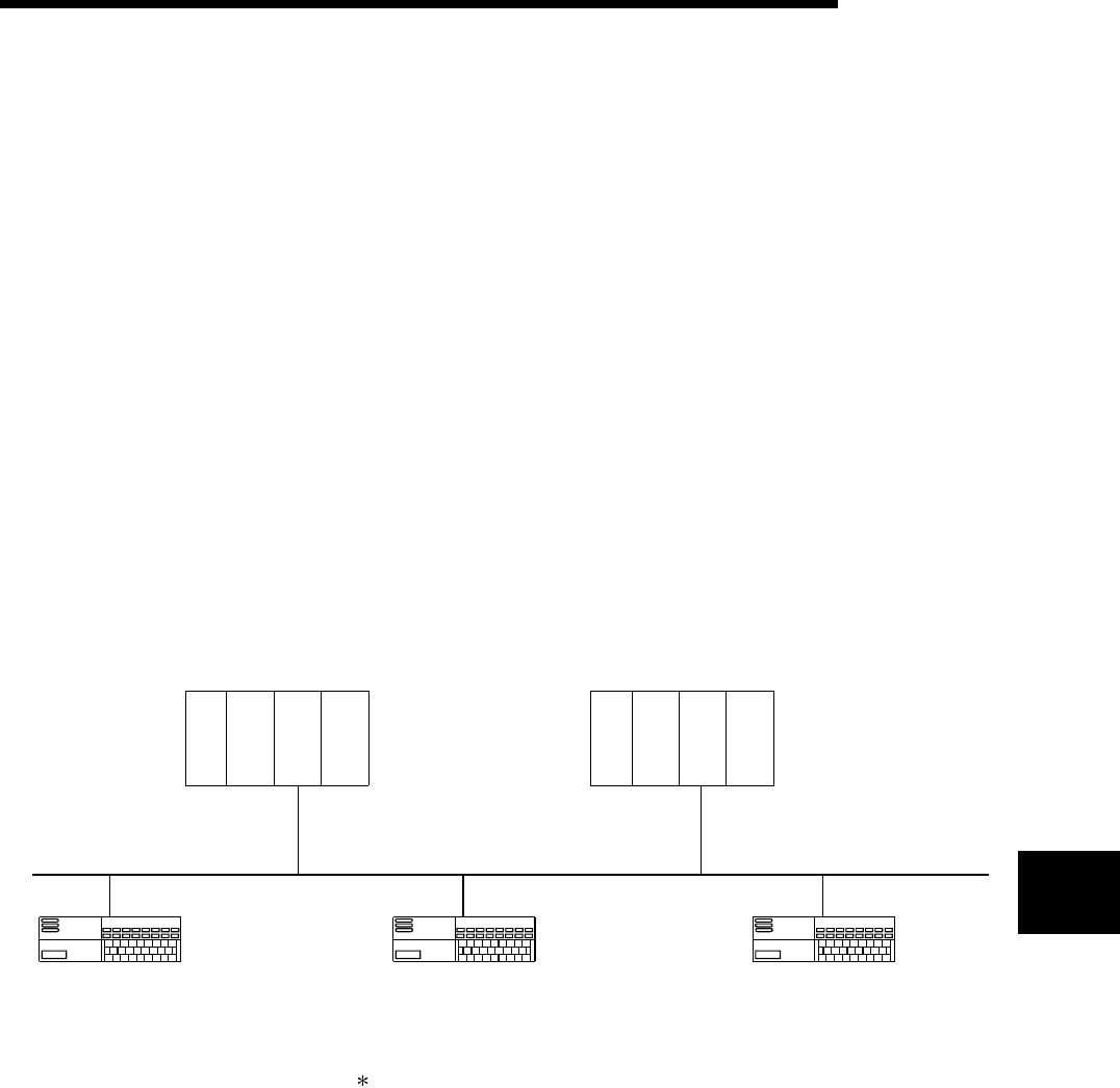
The programs explains in this chapter are based on the following system configuration:
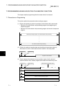
1) The QJ71DN91 (master node) is set to node number 0, the first remote
I/O is set to node number 1, the second remote I/O is set to node
number 2, the third QJ71DN91 (slave node) is set to node number 4,
and the fourth remote I/O is set to node number 3.
2) The QJ71DN91 (master node) and the nodes numbered 1, 2 and 4
perform polling communication, and the QJ71DN91 (master node) and
the node numbered 3 perform bit strobe communication.
3) Input data is assigned to X100 to X16F, and output data is assigned to
Y100 to Y14F.
4) Each node's communication status is stored in M101 to M104.
5) When an error occurs, the system reads that error information into
D500, then stores the node number of the error causing node into D501
and the error code into D502 separately.
6) The attribute data for message communication write is set in D30.
7) It is assumed that the QJ71DN91 (master node) is mounted in slot 0 of
the basic base.
Q61P Q25H
CPU
QJ71
DN91
master
node
No. 0
Q61P Q25H
CPU
QJ71
DN91
slave
node
No. 4
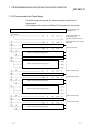
Node No. 1
Omron
CompoBus/D 8-point input
(DRT1-ID08)
Node No. 2
Omron
CompoBus/D 8-point output
(DRT1-0D08)
Node No. 3
Rockwell Automation Japan
Flex I/O DeviceNet adapter + 16-point input
(1794AND + IB16)
The Flex I/O DeviceNet adapter by Rockwell Automation Japan has 2-byte input data
as a status, as well as 2-byte input data and 2-byte output data.