


3 - 14 3 - 14
MELSEC-Q
3 SPECIFICATIONS
3.3.2 Details of the I/O signals
The following describes the ON/OFF timings and conditions of the I/O signals.
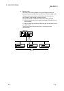
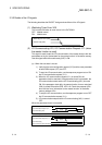
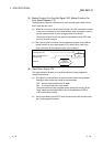
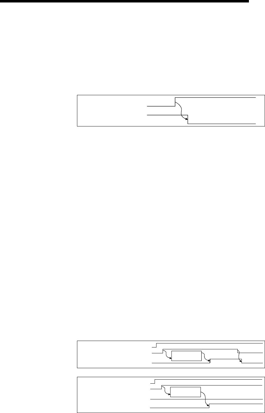
(1) Watchdog Timer Error: X00
This is turned ON when an error occurs in the QJ71DN91.
OFF: Module normal
ON: Module error
W
atchdog timer error (X00)
Module ready (X0F)
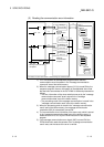
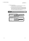
(2) I/O Communicating: X01, I/O Communication Request: Y11 (when
the master function is used)
This signal is used to start the I/O communication of the master function with the
parameters set by the "parameters for the master function" of the buffer memory.
Use this signal while the module ready (X0F) is ON.
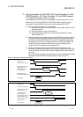
(a) When the auto start is not set:
1) Verify that the auto configuration request (Y15) and the save parameter
to flash ROM request (Y17) are OFF.
2) To start the I/O communication, use the sequence program to turn ON
the I/O communication request (Y11).
3) When the I/O communication request (Y11) is turned ON, the
parameter check is executed. If the parameter check is successful, the
I/O communication starts and the I/O Communicating (X01) is turned
ON. If the parameter check fails, the master function for error set signal
(X03) is turned ON and the ERR. LED is lit. Check the contents of the
error with the "error information for the master function" of the buffer
memory address 1B1
H
.
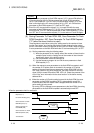
4) To stop the I/O communication, use the sequence program to turn OFF
the I/O communication request (Y11).
5) I/O communication stops and the I/O communicating (X01) is turned
OFF.
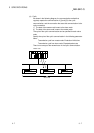
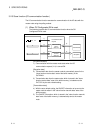
When the parameter check is successful
Module Ready (X0F)
I/O Communication Request (Y11)
I/O Communicating (X01)
Parameter
check
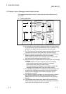
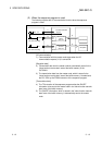
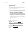
When the parameter check fails
I/O Communicating
I/O Communication Request (Y11)
Module Ready (X0F)
Parameter
check
Master Function For Error Set Signal