


4 - 9 4 - 9
MELSEC-Q
4 SETUP AND PROCEDURES BEFORE OPERATION
4.5 Connecting the Communication Cables to the QJ71DN91
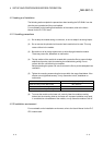
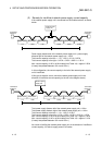
(1) Connecting the communication cables
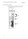
The following explains the connection method of the communication cables to the
QJ71DN91.
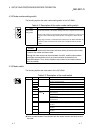
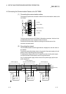
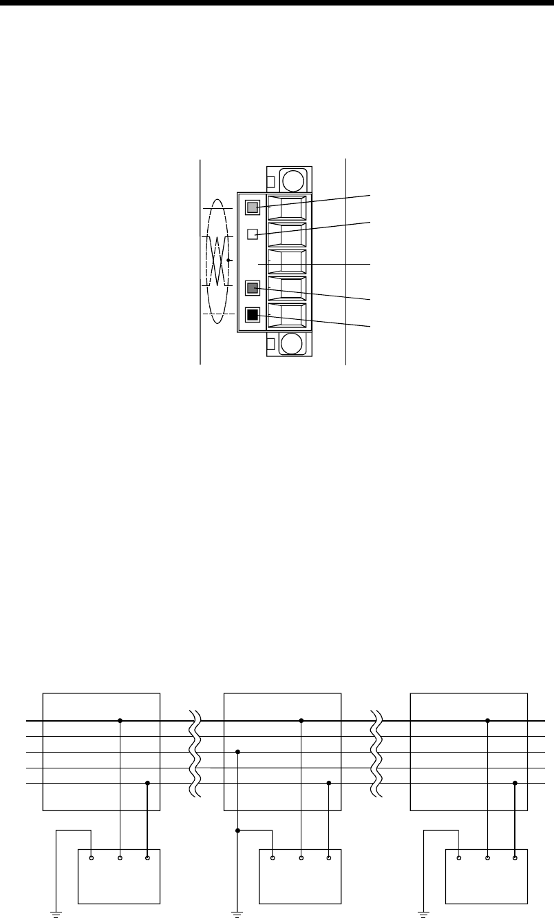
V- (black)
CAN_L (blue)
Shield (drain wire)
CAN_H (white)
V+ (red)
The figure above shows the QJ71DN91's DeviceNet connectors. A sticker in the
corresponding cable color is pasted on each connector.
Connect the communication cables by making sure that the colors of the
connector and cable match.
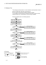
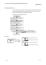
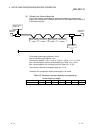
(2) Grounding the network
The DeviceNet network should be grounded at a single point, near the center of
the network.
Connect the cable shield (drain wire) to the ground of the power supply unit, and
perform Class D grounding (Class 3 grounding).
If multiple power supply units exist in a network, ground only the power supply
unit near the center of the network, and do not ground others.
Also, if multiple power supply units are used, use a power supply tap for each
power supply unit.
FG V+ V- FG V+ V-FG V+ V-
Power supply
unit
Power supply tap
Power supply tap
(near the center of the network)
V+
V-
CAN_L
Shield (drain wire)
CAN_H
Power supply tap
Power supply
unit
Power supply
unit