


HELIX DN9848E Remote Control Software
User Guide
83
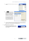
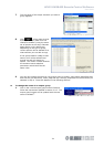
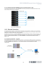
11.2.2 Connecting the HELIX DN9848E units to an Ethernet switch or hub
The diagram below shows each HELIX DN9848E unit directly connected to an Ethernet switch or hub,
which is then connected top a laptop/PC.
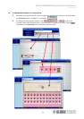
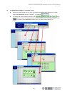
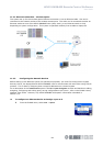
11.3 Ethernet Connection
For familiarisation purposes, a basic Ethernet connection may be made to a single unit by connecting
the Ethernet cable to either of the unit’s rear panel Ethernet sockets and to the network socket on the
laptop PC or wireless access point (wireless option).
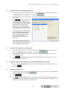
For Ethernet connectivity, the HELIX DN9848E units must be operating V4.00 (or later) host code. For
details on setting up the IP address of the HELIX DN9848E units, please refer to the HELIX DN9848E
System Controller Operators Manual. For HELIX DN9848E unit interconnection details, refer to
section 11.2.
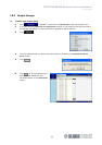
11.3.1 Ethernet connection – standard
The standard system set up is via Ethernet connection. One end of the Ethernet cable is connected to
the network socket of the laptop/PC. The other end is either connected to an Ethernet socket on one of
the HELIX DN9848E units (daisy chain), or an Ethernet switch or hub, depending on system
configuration.