


HELIX DN9848E Remote Control Software
User Guide
42
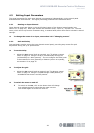
5.3 Setting Output Parameters
Signal processing for each output channel is programmed independently via its associated control panel.
The signal processing parameters are described below.
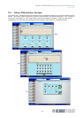
5.3.1 Naming an Output Channel
Channel names are shown in the top left-hand corner of the channel control panels (see section 5.1 on
page 40). The default names are “Output 1”, “Output 2” etc. Each name, which is up to eight
characters in length, is retained after power down and included in stored settings.
To change the name of an output channel, see section 3.2.5 “Changing a name”
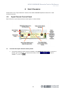
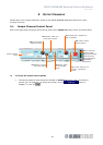
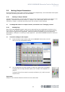
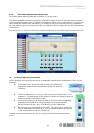
5.3.2 Routing Page
Each of the eight DN9848E outputs’ matrix can be acquired from any combination of the four A, B, C
and D inputs. For paired outputs, the source inputs are attenuated by 6dB prior to summing and the
ratio of the two signals used is adjustable. When all outputs are combined, the source inputs are
attenuated by 12dB prior to summing in equal proportion. (See HELIX DN9848E manual for Technical
Overview).
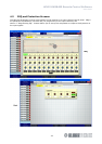
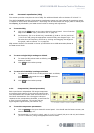
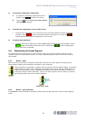
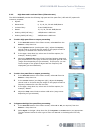
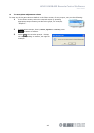
To set the routing for the outputs
1 Press the fader button (shown right) on the DN9848E Units screen; this will
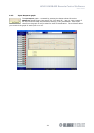
take you to the routing page (below).
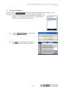
2 You can adjust the mix from scratch or load a mix setting from a template.
To adjust the mix using the latter option, see “To load a mix template” on
page 43.
To adjust the mix from scratch, manually set faders A, B, C and D on each
output to suit.
Important!
Delays for the summed channels must be set to the same value.