


Ð
67 Ð
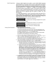
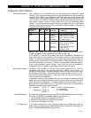
02 ÊÊA EV ZL ZT P
STT Ê 0Ê 0 0 00
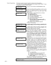
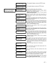
The keypad will display a summary START screen.
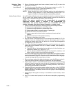
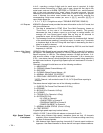
02 ÊÊA EV ZL ZT P
STOP 0 0 0 00
The keypad displays a summary STOP screen.
NOTE: 4204 Relay Module
must be rev. "V3" or higher to
activate temporal pulsing.
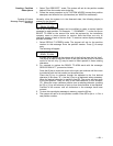
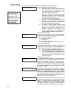
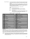
02 RELAY ACTION
NO RESPONSE
Enter the desired relay action as follows:
0=not used; 1=closed for 2 secs.; 2=stay closed;
3=pulse on/off (temporal pulse).
Note: The 4204 relay must have ÒV3Ó later installed
to activate temporal pulse.
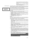
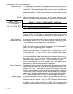
02 START EVENT
NOT USED
Enter the event code to start the relay action as
follows: 0=not used; 1=alarm; 2=fault; 3=trouble;
4=restore
02 START: ZN LIST
NO LIST
If a zone list is being used to start this relay action,
enter the zone list number 1-4. If a zone list is not
being used, enter 0.
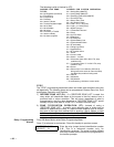
02 START: ZN TYPE
If a zone type/system operation is being used to start
the relay action, enter the 2-digit Zone Type/System
Operation number from the list shown earlier in the
RELAY PROGRAMMING section.
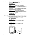
02 START PART
Enter 0 for any partition. Enter 1-2 for specific
partition number.
02 STOP: ZN LIST
NO LIST
If a zone list is being used to stop this relay action,
enter the zone list number 1-4. If a zone list is not
being used, enter 0.
02 STOP: ZN TYPE
If a zone type/system operation is being used to stop
the relay action, enter the 2-digit Zone Type/System
Operation number from the list shown earlier in the
RELAY PROGRAMMING section.
02 STOP PART
Enter 0 for any partition. Enter 1-2 for specific
partition number.
RESTRICTION
1=YES 0=NO
The system may have some devices which are not
intended to be under end user control, such as
relays activating fire doors or machinery. Enter 1 if
the end user will be restricted from accessing this
relay group.
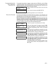
RELAY TYPE
Enter 1 for relays. Enter 2 for X-10 devices.
HOUSE CODE
For X-10 devices, enter the letter house code. A=0,
B=1, C=2, etc. (00-15)
UNIT CODE
For X-10 devices, enter the numerical unit code
(01-15)
ECP ADDRESS
For relay module (4204) outputs, enter the actual
relay module's address set by its DIP switch (01-15).
Up to 2 modules can be installed in a system.
MODULE RELAY #
For relay module (4204) outputs, enter the specific
relay number on that module (1-4).
The keypad displays the two summary screens again.