Ð 20 Ð
2-WIRE POLLING LOOP EXPANSION (Zones 10 through 64)
General Information
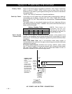
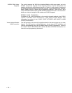
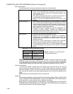
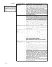
The following table summarizes polling loop expansion characteristics.
Applications ¥ Built-in 2- wire polling loop interface allows the number of
zones to be expanded from the basic 9 zones to up to 64
zones using various Remote Point Modules (RPMs). See
ADVISORIES below.
¥ The polling loop provides power to sensors and serves as
communication path between the panel and sensors.
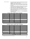
¥ Refer to the list of compatible devices at the end of this
section.
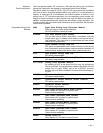
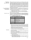
RPM Address (ID) ¥ Each sensor must be assigned a unique address ID number
(from 10-64) before being connected to the polling loop. Care
must be taken to assign unique ID numbers to each sensor in
order to allow the panel to supervise and provide keypad
status indications for individual sensors.
¥ Most RPMs have DIP switches to set their addresses. The
4139SN, 4191SN, 4939SN, 4959SN and 998MX have
preprogrammed serial numbers which must be "enrolled" by
the control via the #93 menu programming mode.
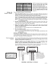
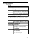
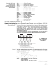
Connections ¥ Connect RPM sensors to terminals 24 & 25.
¥ Sensors can be connected to a single run, or groups of
sensors may be connected to separate wire runs, star
configuration, without affecting the panel's ability to supervise
individual sensors.
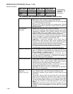
¥ Follow the wiring instructions provided with individual
sensors. Be sure to observe sensor polarity when wiring.
¥ The maximum allowable wire run length between the panel
and the last sensor on a given wire run is shown in the table
below.
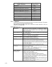
Maximum Polling Loop Wire Runs
Wire Gauge Max. Length
#22 gauge 650 feet
#20 gauge 950 feet
#18 gauge 1500 feet
#16 gauge 2400 feet
Note: Twisted pair recommended
for all normal wire runs.
Important: When in a star configuration, no individual run can be longer than the table
indicates, and the total length of all the sensor star runs, combined, cannot exceed 4000'.
If using shielded wire, the maximum is 2000'. If longer wire runs are needed, a 4197/4297
Loop Extender Module must be used (see instructions included with the 4197/4297).
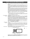
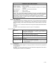
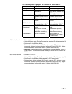
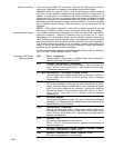
Intercom Interference
If an intercom system is being used, the polling loop wires must be as far from the
intercom wiring as possible (minimum 6"). If this spacing cannot be achieved, shielded
wire must be used. If this is not done, interference on the intercom system might occur.
Also note that the maximum total wire length supported is cut in half when shielded wire is
used.
NOTE: Shield must be terminated at control terminal 30.
Advisories
The maximum allowable current draw from the polling loop is 64mA. Refer to the POLLING
LOOP CURRENT DRAW WORKSHEET (found in the POWERING THE SYSTEM section
of this manual) for current draws of various polling loop devices.
Make certain to include the total current drawn on the polling loop in the AUXILIARY
CURRENT DRAW WORKSHEET (see POWERING THE SYSTEM section) when figuring
the total auxiliary load on the panel's power supply.


