


Ð 23 Ð
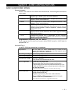
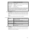
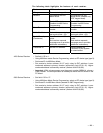
The following table highlights the features of each receiver.
Feature 4281 series 5881 series
Wiring Connects to keypad lines Connects to keypad lines
House ID Programmed via #93
Menu Mode.
Programmed via #93
Menu Mode (needed only
if RF keypad used).
Receiver Address Set via DIP switches.
Enabled via #93 Device
Programming.
Set via DIP switches.
Enabled via #93 Device
Programming.
Cover Removal Does not cause alarm or
trouble.
Does not cause alarm or
trouble.
Go/No Go Mode Automatic upon entering
test mode (code + [5]).
Automatic upon entering
test mode (code + [5]).
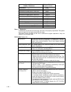
Spatial Diversity
(2 antennas)
Yes. Eliminates nulls and
voids.
2nd receiver expands
coverage area or provides
additional redundancy.
Yes. Eliminates nulls and
voids.
2nd receiver expands
coverage area or provides
additional redundancy.
Transmitter ID Set via DIP switches. Serial numbers are
"enrolled" by the system
or downloaded.
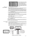
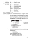
4281 Series Receiver ¥ Set field 1*32 to 1.
¥ Using #93 Menu modeÐDevice Programming, select as RF device type (type 3).
¥ Set house ID via #93 Menu Mode.
¥ Set receiver's device address (01-07 only) using its DIP switches. Lower
numbered address is primary receiver (supervisory fault ID 90, 91). Higher
numbered address is secondary receiver (receiver fault ID 88, 89).
¥ Important: 4281 microprocessor must have part number N5334Vx, where x
is any number. The microprocessor is located just above the DIP switch on the
PC board.
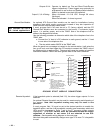
5881 Series Receiver ¥ Set field 1*32 to Ò2Ó.
¥ Using #93 Menu ModeÐDevice Programming, select as RF device type (type 3).
¥ Set house ID via #93 Menu Mode (needed for 5827 keypad only).
¥ Set receiver's device address (01-07 only) using its DIP switches. Lower
numbered address is primary receiver (supervisory fault ID 90, 91). Higher
numbered address is secondary receiver (receiver fault ID 88, 89).