


Ð 29 Ð
A momentary short across this zone will arm the system in the "AWAY" mode. If
the short is held for more than 3 seconds, the system will arm in the "STAY"
mode. After the system has been armed, the next time zone 7 is shorted, the
system will disarm.
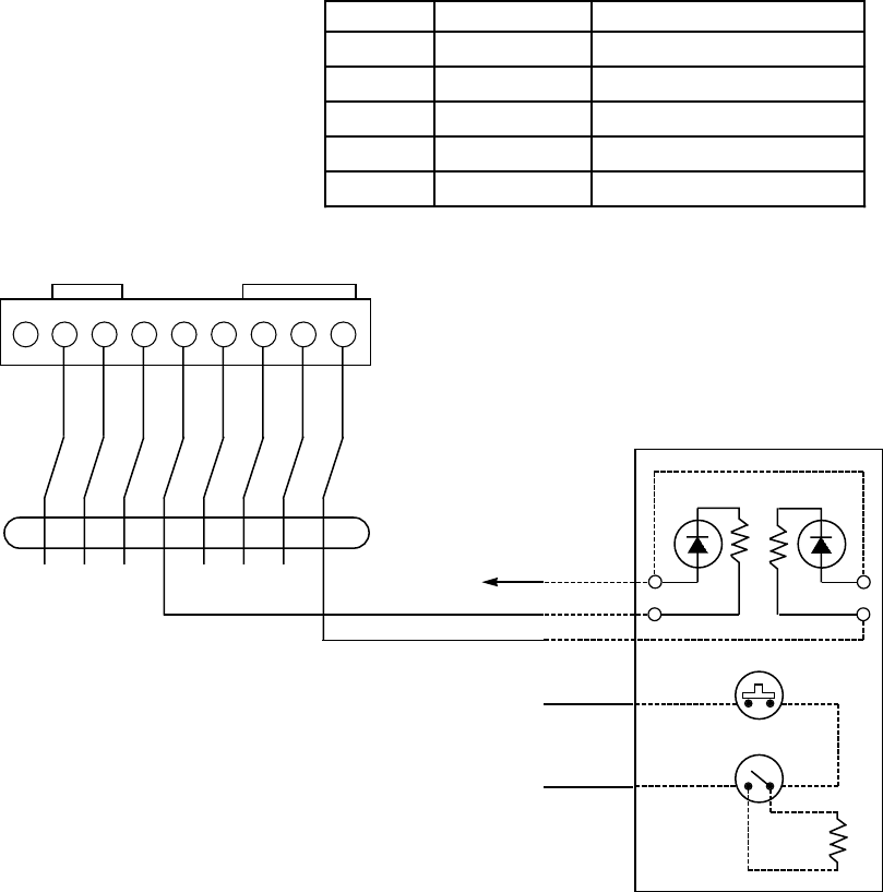
An optional closed-circuit tamper switch (model 112) can be wired in series with
zone 7, so that, if the switchplate is removed from the wall, the tamper will open,
disabling keyswitch operation until the system is next disarmed from the keypad.
Notes:
¥ Only one keyswitch with LEDs can be supported by the system's
power supply.
¥ Open/close reporting for keyswitch is enabled in field *40, and the
keyswitch reports as user Ò0Ó.
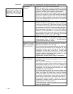
¥ If the keyswitch is used, trigger output 1 can still be used as previously
described in VOLTAGE TRIGGERS section. Trigger outputs 2 & 4 are
used to light the keyswitch LEDs as shown below.
¥ If the keyswitch is used, zone 7 cannot be used as a protection zone.
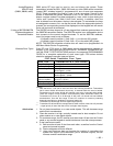
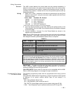
LED indications are defined as follows:
Green Red Meaning
ÊOff Off Disarmed & Not Ready
Ê O n Off Disarmed & Ready
ÊOff On Steady Armed Away
ÊOff Slow Flash Armed Stay
ÊOff Rapid Flash Alarm Memory
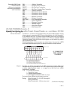
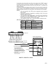
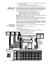
1 2 3 4 5 6 7 8 9
GRAY
YELLOW
WHITE
RED
GREEN
BROWN
BLUE
BLACK
GROUND
OUT 1
GROUND
OUT 2
GROUND
OUT 3
GROUND
OUT 4
J7 CONNECTOR
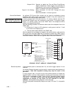
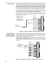
(ARMED) (READY)
RED GREEN
820W 820W
TAMPER
SWITCH (N.C.)
LOCK
SWITCH (N.O.)
2000
OHMS
EOLR
TO TERM 20
TO TERM 19
TO ZONE 7
s
s
{
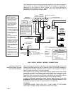
4146 KEYSWITCH
IF KEYSWITCH IS USED.
1. OUT 1 CAN STILL BE USED TO
PROVIDE GROUND START,
OPEN/CLOSE (SEE FIELD 1*46).
2. OUT 2, 3, 4 NO LONGER PROVIDE
ALARM STATUS INDICATIONS. OUT 2
& 4 OPERATE KEYSWITCH LEDs. OUT
3 IS NOT USED. ONLY 1 KEYSWITCH
CAN BE USED.
3. ZONE 7 IS NO LONGER USABLE AS A
PROTECTIVE ZONE.
BROKEN LINES REPRESENT
INSTALLER WIRING CONNECTIONS
N/U
4142TR CABLE
TO AUX POWER
TERMINAL 6
REMOTE KEYSWITCH WIRING