


Ð 113 Ð
++
–
N.C.
N.C.
N.O.
2k EOLR
(note 1)
2k EOLR
(note 1)
+–
+
–
+–
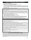
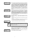
BELL
SIREN
NO CONNECTION
TRANSFORMER
16.5VAC, 40VA
ADEMCO No.1361
(IN CANADA
USE No. 1361CN)
or 4300 TRANS-
FORMER IF X-10
DEVICES
WILL BE USED
Connect to
24-hr. 120VAC,
60 Hz Outlet
Red Blk
Grn Yel
++
–
N.C.
N.C.
2k EOLR
(note 1)
2k EOLR
(note 1)
++
–
N.C.
+
+
–
N.C.
N.C.
2k EOLR
(note 1,4)
TIP
(BROWN)
RING
(GRAY)
TIP
(GREEN)
RING
(RED)
Handset
Incoming
Phone Line
Telephone connections
using Ademco
direct connect cord
and RJ31X jack
(CA38A in Canada)
EARTH GROUND
Connect to good earth
ground to maintain im-
munity to transients.
See Instructions for
proper grounding.
SMOKE
4190
RPM
4278
PIR
Polling loop rating: 64mA
maximum. See Installa-
tion Instructions for
maximum number of
devices supported and
maximum wire run length.
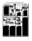
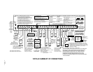
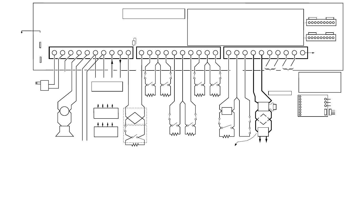
VISTA-40 SUMMARY OF CONNECTIONS
USE UL LISTED ENERGY CABLE FOR ALL CONNECTIONS
Zone resistance (Excluding EOLR):
ZONE 1, 8: 100 OHMS MAX.
ALL OTHER ZONES: 300 OHMS MAX.
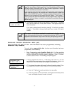
ZONE 1
ZONE 2
ZONE 3 ZONE 4
ZONE 5 ZONE 6 ZONE 7
ZONE 8 ZONE 9
2-WIRE SMOKE
DETECTOR LOOP
(Also supports NO/NC Burg contacts)
POLLING LOOP
Programmable Response
(Fast/Normal) Loop
LATCHING TYPE GLASS
BREAK DETECTOR LOOP
Data in
Data out
12345678910 11121314151617181920 212223242526
27
28 29 30
RED (+)BLK (–)
Connect to
12VDC, 4AH
or 12VDC, 7AH
GEL CELL
BATTERY
CHARGING
VOLTAGE
13.7 VDC
See
Installation
Instructions for
required
battery capacity
Replace
every
3 years
NOTE:
WHEN POWERING UP
THE PANEL, PLUG THE
TRANSFORMER IN BEFORE
CONNECTING THE BATTERY.
See Installation Instructions
for type & max # of keypads,
and for max wire run length.
ALARM SOUNDER OUTPUT
10VDC-13.8 VDC,2.8A max.
Note: Combined alarm and auxilary
power output current must be limited
to 750mA for UL installations.
AUXILARY POWER OUTPUT
9.6VDC - 13.8VDC,750 mA max.
Note: Include current drawn
by keypads and polling loop
devices when making
auxiliary power calculations.
+
–
NOTES:
1. Zone 1 may be selected for EOLR supervised
or normally closed (no EOLR) operation via cut
jumper. (Cut red jumper for normally closed operation.
Do not cut for Fire Usage). Zones 2-8 may be selected
for either operation via program field
*
41.
Zone 1 supports 2-wire smoke detectors.
See Installation Instructions for recommended type
and maximum number of detectors supported.
Zone 7 may be used for remote keyswitch arming/disarming.
See Installation Instructions for wiring instructions.
Zone 8 supports 2-wire latching type glass break detectors.
See Installation Instructions for recommended type and
maximum number of detectors supported.
2.
3.
4.
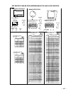
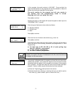
1 2 3 4 5 6 7 8 9
1. Not Used
2. Ground-
3. Out 1 (Ground Start)
4. Ground-
5. Out 2 (fire)
6. Ground-
7. Out 3 (burg/aud. panic)
8. Ground
9. Out 4 (silent panic/
duress)
Optional programming:
Out 1: Open/close or Keypad-like sounding
Out 2: Armed LED
Out 4: Ready LED
Ratings for Out 1:
Active: 10VDC-13.8VDC through 4k OHMS
Not Active: 100 OHMS to ground
Ratings for out 2-4:
Active: 10VDC-13.8VDC through 5k OHMS
Not Active: 1k OHMS to ground
N.C.
N.O.
N.O. N.O.
2k EOLR
(note 1,2)
N.O. N.O.
N.O.
N.C.
N.O.
2k EOLR
(note 1)
2k EOLR
(note 1,3)
N.C.
+
–
J7
GLASS
BREAK
1 2 3 4 5 6 7 8 9
J8
MAKE CONNECTIONS USING
No. 4142TR CABLE
WARNING: OWNER'S INSTRUCTION NOTICE NOT TO BE REMOVED
Fire
Usage
Burg.
Usage
CONNECTION OF THE FIRE ALARM SIGNAL TO A FIRE
ALARM HEADQUARTERS OR A CENTRAL STATION SHALL
BE PERMITED ONLY WITH THE APPROVAL OF THE LOCAL
AUTHORITY HAVING JURISDICTION. THE BURGLAR ALARM
SIGNAL SHALL NOT BE CONNECTED TO A POLICE
EMERGENCY NUMBER.
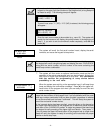
1. In 2
2. Ground
3. In 3 (4300 sync)
4. In 4 (4300 sync)
5. Ground
6. Out 5 (4300 data)
7. Out 6
8. Ground
9. Ground
Red Jumper
(note 1)
DOC LOAD No.: 5
J7 Header J8 Header
BATTERY
TABS
4192SD
SMOKE
WARNING: TO PREVENT
RISK OF ELECTRICAL
SHOCK, DISCONNECT
TELCO JACK BEFORE
SERVICING THIS PANEL.
THIS EQUIPMENT SHOULD BE INSTALLED IN ACCORDANCE
WITH THE NATIONAL FIRE PROTECTION ASSOCIATION'S
STANDARD 74 (NATIONAL FIRE PROTECTION ASSOC.,
BATTERYMARCH PARK.QUINCY, MA. 02269). PRINTED
INFORMATION DESCRIBING PROPER INSTALLATION,
OPERATION, TESTING, MAINTENANCE, EVACUATION
PLANNING AND REPAIR SERVICE IS TO BE PROVIDED WITH
THIS EQUIPMENT.
FOR COMPLETE INFORMATION,
SEE INSTRUCTIONS N7001-INSTV2
WEEKLY TESTING IS REQUIRED TO ENSURE PROPER OPERATION OF THIS SYSTEM.
COMPLIES WITH FCC RULES, PART 68
FCC REGISTRATION NO. AC398U-68192-AL-E
RINGER EQUIVALENCE: 0.7B
THIS DEVICE COMPLIES WITH PART 15 OF
FCC RULES. OPERATION IS SUBJECT TO THE
FOLLOWING TWO CONDITIONS: (1) IT MAY NOT
CAUSE HARMFUL INTERFERENCE.
(2) IT MUST ACCEPT ANY INTERFERENCE THAT
MAY CAUSE UNDESIRED OPERATION.
(Refer to Installation Instructions for information concerning Direct Wire
Downloading using the 4100SM Serial Module.)
ALL CIRCUITS ARE
POWER LIMITED.
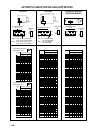
REMOTE KEYPAD
(Addressable keypads)
Zone response time:
ZONES 1-8: 350mSec-500mSec, or 720mSec
ZONE 9: Programmable for
Fast: 10mSec-15mSec
Normal: 350mSec-500mSec, or 720mSec
(default response)
NOTE:
Zone 5 supports
AAV Triggering
(Zone Type 10)
See I.I. for Pro-
gramming and
Wiring Inform-
ation.
OPTIONAL
VOICE
INTERFACE
MODULE
(VIM)
TO
CONTROL'S
KEYPAD
TERMINALS
(6, 7, 8, 9)
SEE INSTRUCTIONS
FOR WIRING DETAILS
TO GND TERM 30
TO HANDSET
TERMINAL'S 26 & 27
{
TO
6139AV
2-WAY
VOICE
KEYPADS
(UP TO 6)
OPTIONAL
4285 PHONE
MODULE
OPTIONAL
4281/5881/5882
RF RECEIVER
SEE INSTRUCTIONS
FOR WIRING DETAILS
TO
TO: 6 7 8 9
TO: 6 7 8 9