


Ð 10 Ð
Section 2. INSTALLING THE CONTROL
MOUNTING THE CABINET
General The VISTA-40 is supplied with a 12.5"W x 14.5"H x 3"D cabinet suitable for use
in residential and non-certified commercial burglary installations.
Mount the Control cabinet to a sturdy wall using fasteners or anchors (not
supplied) in a clean, dry area which is not readily accessible to the general public.
The back of the Control cabinet has 4 holes for this purpose.
Follow the instructions below for mounting the VISTA-40 PC board into the
cabinet and for mounting the Control's lock to its cabinet door.
Mounting The
PC Board
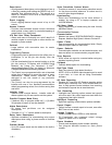
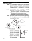
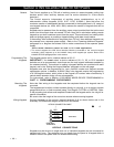
Before mounting the circuit board, be certain that the appropriate metal
knockouts have been removed. Do not attempt to remove the
knockouts after the circuit board has been installed.
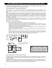
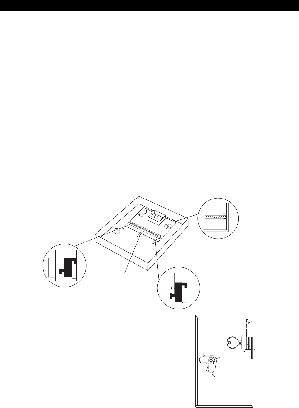
1. Hang the three mounting clips on the raised cabinet tabs. Observe proper
clip orientation to avoid damage to the clip when mounting screws are
tightened and to avoid problems with insertion and removal of the PC board.
2. Insert the top of the circuit board into the slots at the top of the cabinet. Make
certain that the board rests in the slots as indicated in step 2 detail.
3. Swing the base of the board into the mounting clips and secure the board to
the cabinet with the accompanying screws (as illustrated in step 3 detail).
Advisory Make certain that the mounting screws are reasonably tight to ensure that there is
a good ground connection between the PC board and the cabinet. Also, dress
field wiring away from the microprocessor (center) section of the PC board. The
cabinet provides 2 loops on its left and right sidewalls for anchoring field wiring
using tie wraps. These steps are important to minimizing the risk of panel RF
interference with television reception.
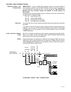
A
B
3RD CLIP
REQUIRED
DETAIL SIDE VIEW OF CLIP INSTALLATION
A-CABINET TAB WITHOUT CLIP
B-CABINET TAB WITH HANGING CLIP
DETAIL SIDE VIEW OF CLIP AND
BOARD INSTALLED
DETAIL SIDE
VIEW OF BOARD
INSERTED INTO
SLOTS
MOUNTING THE PC BOARD
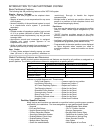
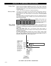
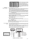
Installing the Lock
1. Remove the lock knockout on the
control cabinet cover. Insert the key
into the lock. Position the lock in the
hole making certain that the latch will
make contact with the latch bracket
when the door is closed.
2. While holding the lock steady, insert
the retainer clip into the retainer
slots.
3. Hold the lock steady, and insert the
retainer clip into the retainer slots.
Position the clip as illustrated in
order to permit easy removal.
CABINET DOOR BOTTOM
RETAINER
CLIP
RETAINER CLIP
(NOTE POSITION)
RETAINER
SLOTS
LOCKED
UNLOCKED