


Operating Instructions Teledyne API Model T360/T360M Operation Manual
70
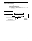
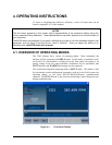
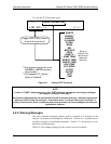
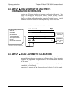
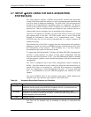
To view the TEST Functions press:
RANGE
RANGE1
1
RANGE2
1
O
2
RANGE
STABIL
MEAS
REF
MR RATIO
PRES
SAMP FL
SAMP TEMP
BENCH TEMP
WHEEL TEMP
BOX TEMP
PHT DRIVE
SLOPE
OFFSET
TEST
TIME
SAMPLE RANGE = 500.000 PPM CO2 = XXX.X
< TST TST > CAL SETUP
1
Only appears instrument is set
for DUAL or AUTO reporting
range modes.
2
Only appears if O
2
Sensor
Option is installed.
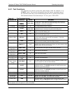
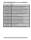
Refer to
Table 6-2 for
definitions of
these test
functions.
Toggle <TST TST> buttons
to scroll throu
g
h list of
Figure 4-2: Viewing TEST Functions
NOTE
A value of “XXXX” displayed for any of the TEST functions indicates an out-of-range reading or
the analyzer’s inability to calculate it.
All pressure measurements are represented in terms of absolute pressure. Absolute, atmospheric
pressure is 29.92 in-Hg-A at sea level. It decreases about 1 in-Hg per 300 m gain in altitude. A
variety of factors such as air conditioning and passing storms can cause changes in the absolute
atmospheric pressure.
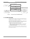
4.2.2. Warning Messages
The most common instrument failures will be reported as a warning on the
analyzer’s front panel and through the COM ports. Section 8.1.1 explains how to
use these messages to troubleshoot pr
oblems. Section 3.7.3 shows how to view
and clear warn
ing messages.
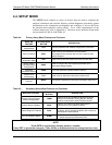
Table 4-3 lists warning messages for the current version of software.
07272B DCN6552