


Principles of Operation Teledyne API Model T360/T360M Operation Manual
204
7.4. ELECTRONIC OPERATION
7.4.1. Overview
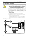
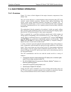
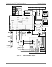
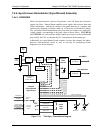
Figure 7-11 shows a block diagram of the major electronic components of the
Model T360.
The core of the analyzer is a microcomputer/central processing unit (CPU) that
controls various internal processes, interprets data, makes calculations, and
reports results using specialized firmware developed by Teledyne API. It
communicates with the user as well as receives data from and issues commands
to a variety of peripheral devices via a separate printed circuit assembly called the
Motherboard.
The motherboard, directly mounted to the analyzer’s inside rear panel, collects
data, performs signal conditioning duties and routs incoming and outgoing signals
between the CPU and the analyzer’s other major components.
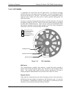
Data is generated by a gas-filter-correlation optical bench which outputs an
analog signal corresponding to the concentration of CO
2
in the sample gas. This
analog signal is transformed into two, pre-amplified, DC voltages (CO2 MEAS
and CO2 REF) by a synchronous demodulator printed circuit assembly. CO2
MEAS and CO2 REF are converted into digital data by a unipolar, analog-to-
digital converter, located on the mother board.
A variety of sensors report the physical and operational status of the analyzer’s
major components, again through the signal processing capabilities of the mother
board. These status reports are used as data for the CO
2
concentration calculation
and as trigger events for certain control commands issued by the CPU. They are
stored in memory by the CPU and in most cases can be viewed but the user via
the front panel display.
The CPU communicates with the user and the outside world in a variety of
manners:
Through the analyzer’s touchscreen and LCD display over a clocked, digital,
serial I/O bus (using a protocol called I
2
C)
RS 232 & RS485 Serial I/O channels via Ethernet, Modbus
®
, Apicom or a
terminal emulation program
Various DCV and DCA analog outputs, and
Several sets of Digital I/O channels.
Finally, the CPU issues commands via a series of relays and switches (also over
the I
2
C bus) located on a separate printed circuit assembly to control the function
of key electromechanical devices such as heaters, motors and valves.
07272B DCN6552