


Principles of Operation Teledyne API Model T360/T360M Operation Manual
210
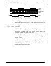
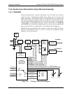
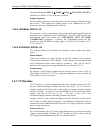
7.4.4. Synchronous Demodulator (Sync/Demod) Assembly
7.4.4.1. OVERVIEW
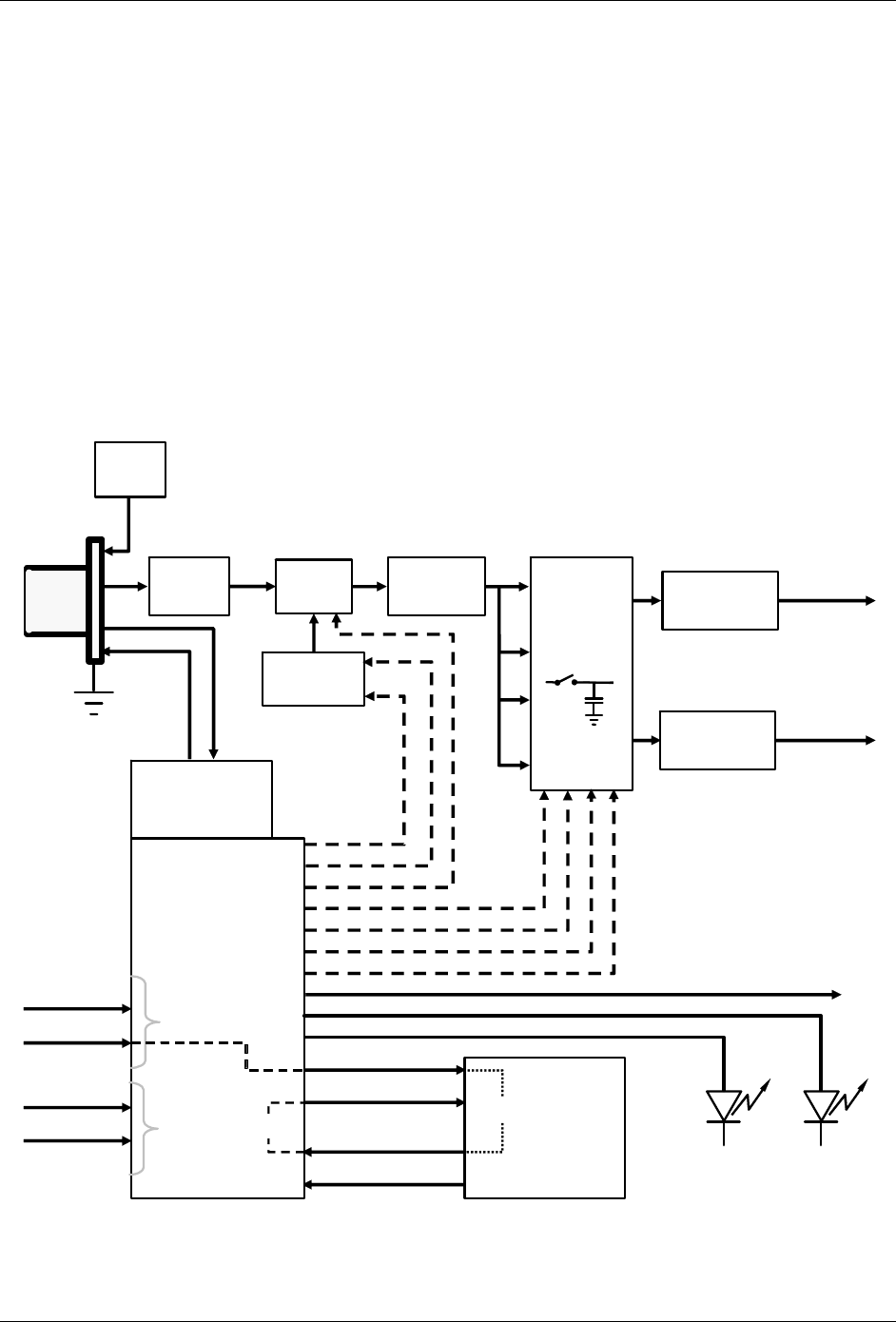
While the photo-detector converts fluctuations of the IR beam into electronic
signals, the Sync / Demod Board amplifies these signals and converts them into
usable information. Initially the output by the photo-detector is a complex and
continuously changing waveform made up of Measure and Reference pulses.
The sync/demod board demodulates this waveform and outputs two analog DC
voltage signals, corresponding to the peak values of these pulses. CO2 MEAS
and CO2 REF are converted into digital signals by circuitry on the motherboard
then used by the CPU to calculate the CO
2
concentration of the sample gas.
Additionally the synch/demod board contains circuitry that controls the photo-
detector’s thermoelectric cooler as well as circuitry for performing certain
diagnostic tests on the analyzer.
Thermo-Electric
Cooler
Control Circuit
Sample &
Hold
Circuits
(x4)
Amplifiers
Dark
Switch
Photo-
detector
Pre Amp
Phase
Lock
Loop
E-Test
Generator
Compact
Programmable
Logic Device
M/R Sensor
Segment
Sensor
E Test Control
Dark Switch
Control
X10 Clock
Phase Lock
E Test A Gate
Dark Test Gate
X1 Reference
Segment
Status LED
Phase Lock Warning
M/R
Status LED
Segment Clock
E Test B Gate
Measure Gate
Measure Dark Gate
Reference Gate
Reference Dark Gate
CO
2
MEAS
CO
2
Reference
56V
Bias
Variable
Gain Amp
From GFC
Wheel
From CPU
via Mother
Board
Signal
Conditioner
Signal
Conditioner
10
x10
TEC Control
PHT DRIVE
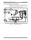
Figure 7-15: T360 Sync / Demod Block Diagram
07272B DCN6552