


Getting Started Teledyne API Model T360/T360M Operation Manual
36
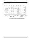
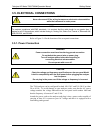
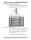
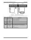
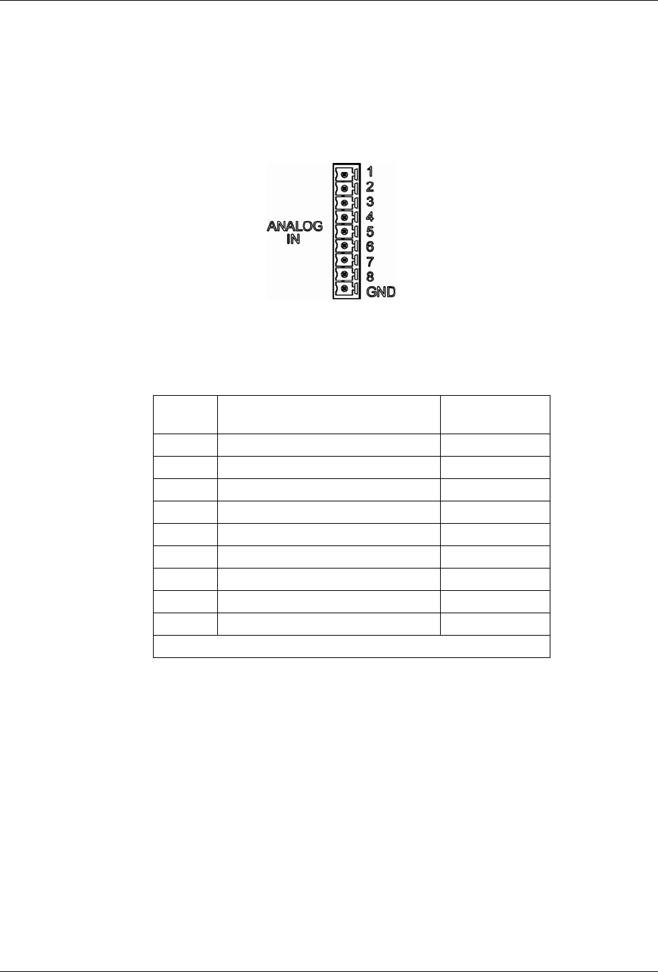
3.5.2. Connecting Analog Inputs (Option 64B)
The Analog In connector is used for connecting external voltage signals from
other instrumentation (such as meteorological instruments) and for logging these
signals in the analyzer’s internal data acquisition system (DAS). The input
voltage range for each analog input is 0-10 VDC, and the input impedance is
nominally 20kΩ in parallel with 0.1µF.
Figure 3-7: Analog In Connector
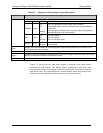
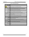
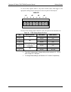
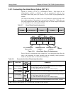
Pin assignments for the Analog In connector are presented in Table 3-3.
Table 3-3: Analog Input Pin Assignments
PIN DESCRIPTION
DAS
PARAMETER
1
1 Analog input # 1 AIN 1
2 Analog input # 2 AIN 2
3 Analog input # 3 AIN 3
4 Analog input # 4 AIN 4
5 Analog input # 5 AIN 5
6 Analog input # 6 AIN 6
7 Analog input # 7 AIN 7
8 Analog input # 8 AIN 8
GND Analog input Ground N/A
1
See Section 4.7 for details on setting up the DAS.
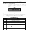
3.5.3. Connecting Analog Outputs
The T360 is equipped with several analog output channels accessible through a
connector on the back panel of the instrument. The standard configuration for
these outputs is mVDC. An optional current loop output is available for each.
When the instrument is in its default configuration, channels A1 and A2 output a
signal that is proportional to the CO
2
concentration of the sample gas. Either can
be used for connecting the analog output signal to a chart recorder or for
interfacing with a data logger.
Output A3 is only used if the optional O
2
sensor is installed.
Channel A4 is special. It can be set by the user (see Section 4.13.9) to output any
one of the para
meters accessible through the <TST TST> menu (Table 4-2).
07272B DCN6552