


Teledyne API Model T360/T360M Operation Manual Calibration Procedures
173
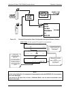
5.3. MANUAL CALIBRATION CHECKS
Informal calibration checks, which only evaluate but do not alter the analyzer’s
response curve, are recommended as a regular maintenance item and in order to
monitor the analyzer’s performance. To carry out a calibration check rather than
a full calibration, follow these steps.
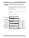
STEP ONE: Connect the sources of zero air and span gas as shown in Figures
7.1 or 7.2.
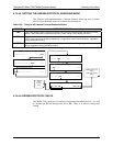
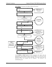
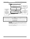
STEP TWO: Perform the zero/span calibration check procedure:
SAMPLE STABIL=XXX.X PPM CO2=X.XXX
< TST TST > CAL SETUP
ACTION:
Record the CO
2
concentration
reading.
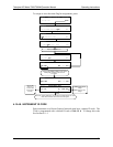
A
CTION:
Supply span gas to the instrument
SAMPLE STABIL=XXX.X PPM CO2=X.XXX
< TST TST > CAL SETUP
ACTION:
Record the CO
2
concentration
reading.
Wait until
STABIL is
below 1.0 ppm.
This may take
several minutes.
The value of
STABIL may jump
significantly.
Wait until it falls
below 1.0 ppm. This
may take several
minutes.
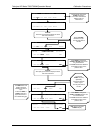
SAMPLE STABIL=XXX.X PPM CO2=X.XXX
< TST TST > CAL SETUP
The SPAN key appears during the transition from zero to
span. You may see both SPAN and ZERO buttons.
SAMPLE RANGE = 500.0 PPM CO2=X.XXX
< TST TST > CAL SETUP
Scroll the display to the
STABIL test function.
A
CTION:
Supply the instrument with zero gas.
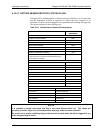
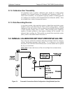
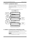
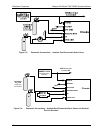
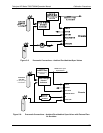
5.4. MANUAL CALIBRATION WITH ZERO/SPAN VALVES
There are four different zero/span valve option configurations (see Figure 5-3
through Figure 5-6). They all operate identically, differing onl
y in the method
used to supply calibration gas to the Analyzer.
STEP ONE
: Connect the sources of Zero Air and Span Gas as shown below.
Figure 5-3 through Figure 5-6 show the proper pneumatic connections for T36
0s
with various optional internal valve sets installed.
07272B DCN6552