


Troubleshooting and Service Teledyne API Model T360/T360M Operation Manual
224
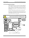
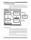
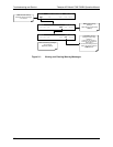
5. Follow the procedures defined in Section 8.5 for confirming that the
analyzer’s basic components are working (power supplies, CPU, relay board,
sync/demod board, touchscreen/display, GFC wheel motor, etc.). See
Figure 3-5 for general layout of compon
ents an
d sub-assemblies in the
analyzer. See the wiring list and diagram in Appendix D of this manual.
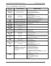
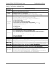
8.1.1. Interpreting WARNING Messages
The most common and/or serious instrument failures will result in a warning
message being displayed on the front panel. Table 8-1 lists warning messages,
along with th
eir meaning and recommended corrective action.
It should be noted that if more than two or three warning messages occur at the
same time, it is often an indication that some fundamental analyzer sub-system
(power supply, relay board, motherboard) has failed rather than indication of the
specific failures referenced by the warnings. In this case, it is recommended that
proper operation of power supplies (see Section 8.5.2), the relay board (see
Section 8.5.6), and the A/D Board (see Section 8.5.8.1) be confirmed before
addressing the specific wa
rning messages.
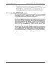
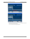
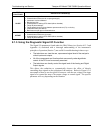
The analyzer will alert the user that a Warning message is active by flashing the
FAULT LED and displaying the Warning message in the Param field along with
the CLR button (press to clear Warning message). The MSG button displays if
there is more than one warning in queue or if you are in the TEST menu and have
not yet cleared the message. The following display/touchscreen examples provide
an illustration of each:
07272B DCN6552