


Getting Started Teledyne API Model T360/T360M Operation Manual
54
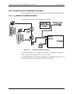
4. Remove the cap from the second, unused, output port on the pressure
regulator.
5. Attach a pressure gauge capable of measuring in the 5-10 psig range with
0.5 psig resolution to the port.
6. Turn the instrument on.
7. Make sure the zero air supply to the analyzer’s purge line inlet is supplying
gas at a stable pressure above 7.5 psig.
8. Adjust the T360’s pressure regulator until the attached gauge reads 7.5 psig.
9. Turn off the instrument.
10. Remove the source of zero air attached to the purge line inlet port at the
back of the analyzer.
11. Remove the pressure gauge and reattach the end cap removed in step 4
above.
12. Replace the analyzer’s top cover.
3.7. INITIAL OPERATION
If you are unfamiliar with the T360 principles of operation, we recommend that
you read Section 7. For information on navigating the analyzer’s software
menus, see the
menu trees described in Appendix A.
NOTE
The analyzer’s cover must be installed to ensure that the temperatures of the GFC wheel and
absorption cell assemblies are properly controlled.
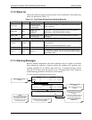
3.7.1. Startup
After electrical and pneumatic connections are made, and initial functional check
is required. Turn on the instrument. The pump, exhaust fan and PMT cooler fan
should start immediately. The display will briefly show a logo splash screen at
the start of initialization.
The analyzer should automatically switch to Sample Mode after completing the
boot-up sequence and start monitoring CO
2
gas. However, there is an
approximately one hour warm-up period before reliable gas measurements can be
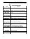
taken. During the warm-up period, the front panel display may show messages in
the Parameters field.
07272B DCN6552