


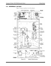
Teledyne API Model T360/T360M Operation Manual Getting Started
37
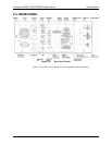
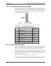
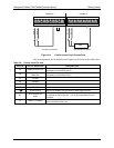
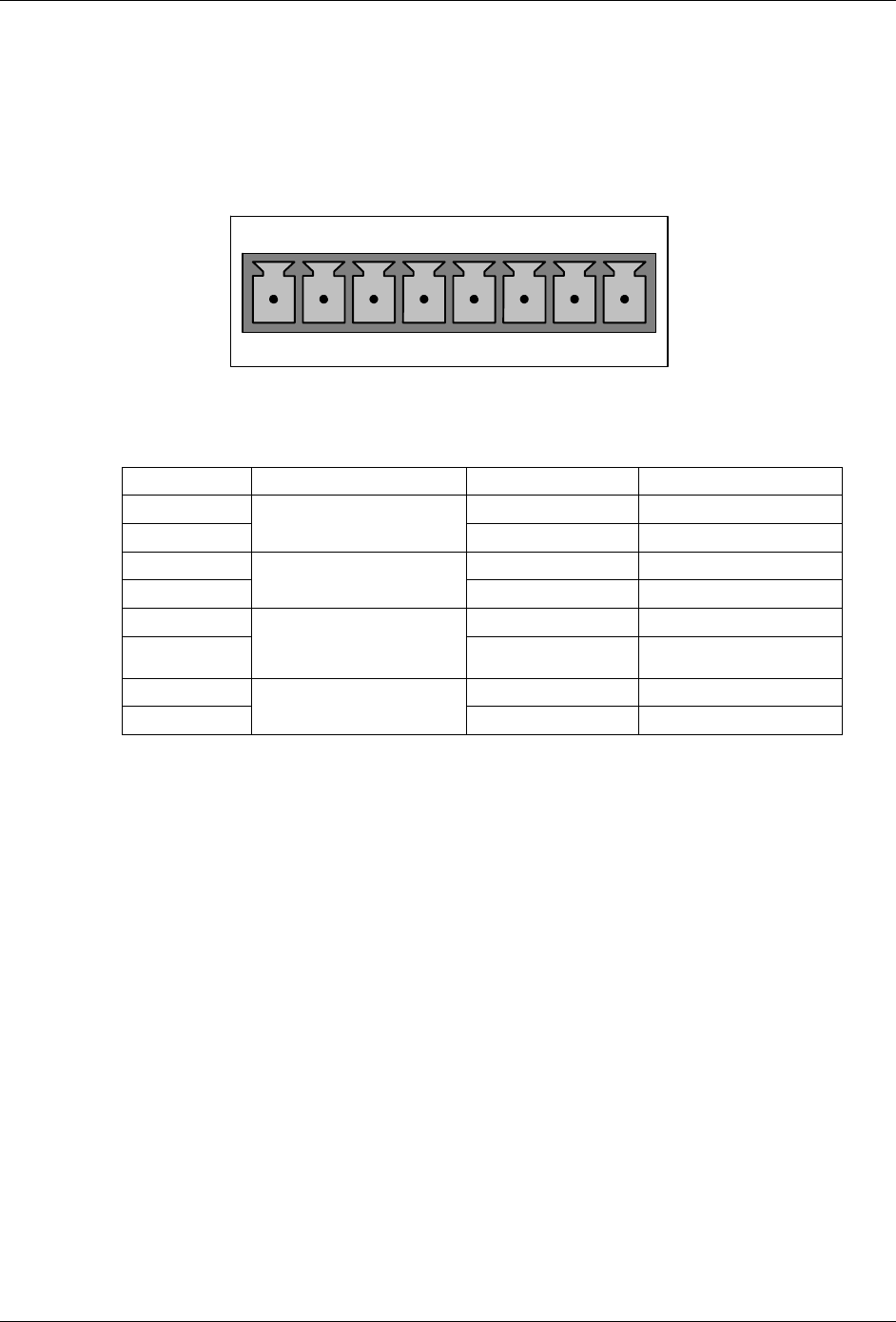
To access these signals attach a strip chart recorder and/or data-logger to the
appropriate analog output connections on the rear panel of the analyzer.
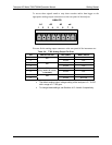
ANALOG
A1 A2 A3
A
4
1 2 3 4 5 6 7 8
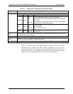
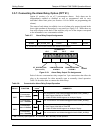
Pin-outs for the analog output connector at the rear panel of the instrument are:
Table 3-4: T360 Analog Output Pin Outs
PIN ANALOG OUTPUT VDC SIGNAL MADC SIGNAL
1 V Out I Out +
2
A1
Ground I Out -
3 V Out I Out +
4
A2
Ground I Out -
5 V Out I Out +
6
A3
(Only used if O
2
sensor
is installed)
Ground I Out -
7 V Out Not used
8
A4
Ground Not used
The default analog output voltage setting of the analyzer is 0 – 5 VDC
with a range of 0 – 500 ppm.
To change these settings, see Sections 4.13.4 and 4.8 respectively.
07272B DCN6552