


223
8. TROUBLESHOOTING AND SERVICE
This contains a variety of methods for identifying the source of performance
problems with the analyzer. Also included in this are procedures that are used in
repairing the instrument.
CAUTION
The operations outlined in this section are to be performed by qualified
maintenance personnel only.
CAUTION
Risk of electrical shock. Disconnect power before performing the
following operations.
8.1. GENERAL TROUBLESHOOTING HINTS
The analyzer has been designed so that problems can be rapidly detected,
evaluated and repaired. During operation, the analyzer continuously performs
self-check diagnostics and provides the ability to monitor the key operating
parameters of the instrument without disturbing monitoring operations.
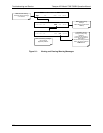
A systematic approach to troubleshooting will generally consist of the following
four steps:
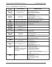
1. Note any WARNING MESSAGES and take corrective action as required.
2. Examine the values of all
TEST functions and compare to factory values.
Note any major deviations from the factory values and take correction action
as required.
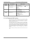
3. Use the internal electronic status LED’s to determine whether the CPU and
I
2
C buses are running, and if the sync/demodulator and relay board are
operating properly. Verify that the DC power supplies are operating properly
by checking the voltage test points on the relay board. Please note that the
analyzer’s DC power wiring is color-coded and these colors match the color
of the corresponding test points on the relay board.
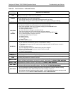
4.
SUSPECT A LEAK FIRST! Data from Teledyne API’s Technical Support
department indicates that 50% of all problems are eventually traced to leaks
in the pneumatic connections and gas lines of the analyzer itself, the source
of zero air, span gases or sample gas delivery system.
Check for gas flow problems such as clogged or blocked internal/external
gas lines, damaged seals, punctured gas lines, a damaged pump diaphragm,
etc.
07272B DCN6552