


Operating Instructions Teledyne API Model T360/T360M Operation Manual
136
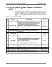
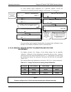
The following DC current output limits apply to the current loop modules:
Table 4-17: Analog Output Current Loop Range
RANGE MINIMUM OUTPUT MAXIMUM OUTPUT
0-20 mA 0 mA 20 mA
These are the physical limits of the current loop modules, typical
applications use 2-20 or 4-20 mA for the lower and upper limits. Please
specify desired range when ordering this option.
The default offset for all ranges is 0 mA.
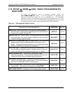
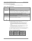
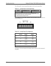
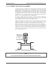
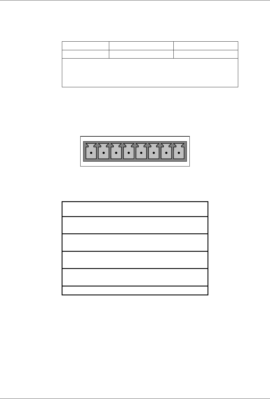
Pin assignments for the output connector at the rear panel of the instrument are
shown in Table 4-18.
ANALOG OUT
A1 A2 A3 A4
+ - + - + - + -
Table 4-18: Analog Output Pin Assignments
PIN
ANALOG
OUTPUT
VOLTAGE
SIGNAL
CURRENT
SIGNAL
1 V Out I Out +
2
A1
Ground I Out -
3 V Out I Out +
4
A2
Ground I Out -
5 V Out I Out +
6
A3
1
Ground I Out -
7 V Out Not used
8
A4
Ground Not used
1
Output A3 is only used when the O
2
sensor option is installed
See Figure 3-4 for the location of the analog output connector on the instrument’s
rear panel.
07272B DCN6552