


Teledyne API Model T360/T360M Operation Manual Maintenance Schedule and Procedures
191
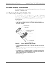
6.3.2. Rebuilding the Sample Pump
The diaphragm in the sample pump periodically wears out and must be replaced.
A sample rebuild kit is available – see Appendix B of this manual for the part
number of the pump rebuild kit. Instructions and diagrams are included with the
kit.
Always perform a Flow and Leak Check after rebuilding the Sample Pump.
6.3.3. Performing Leak Checks
Leaks are the most common cause of analyzer malfunction; Section 6.3.3.1
presents a simple leak check procedure. Section 6.3.3.2 details a more thorough
procedure.
6.3.3.1. VACUUM LEAK CHECK AND PUMP CHECK
This method is easy and fast. It detects, but does not locate most leaks; it also
verifies that the sample pump is in good condition.
1. Turn the analyzer ON, and allow enough time for flows to stabilize.
2. Cap the sample inlet port.
3. After several minutes, when the pressures have stabilized, note the following.
In the
TEST menu, note the SAMPLE PRESSURE reading.
4. If the reading is < 10 in-Hg, the pump is in good condition and there are no
large leaks.
5. Check the sample gas flow. If the flow is <10 cm
3
/min and stable, there are
no large leaks in the instrument’s pneumatics.
6.3.3.2. PRESSURE LEAK CHECK
If you can’t locate the leak by the above procedure, use the following procedure.
Obtain a leak checker similar to the Teledyne API part number 01960, which
contains a small pump, shut-off valve, and pressure gauge. Alternatively, a
convenient source of low-pressure gas is a tank of span gas, with the two-stage
regulator adjusted to less than 15 psi with a shutoff valve and pressure gauge.
CAUTION
Do not use bubble solution with vacuum applied to the analyzer. The
solution may contaminate the instrument. Do not exceed 15 PSIG
pressure.
1. Turn OFF power to the instrument.
2. Install a leak checker or tank of gas as described above on the sample inlet
at the rear panel.
3. Remove the instrument cover and locate the inlet side of the sample pump.
Remove the flow assembly from the pump and plug it with the appropriate
gas-tight fitting.
07272B DCN6552