


Teledyne API Model T360/T360M Operation Manual Operating Instructions
135
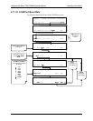
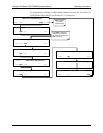
4.13.4. Analog I/O Configuration
The analog I/O functions that are available in the T360 are:
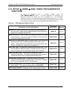
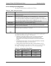
Table 4-15: DIAG - Analog I/O Functions
Sub Menu Function
AOUTS CALIBRATED: Shows the status of the analog output calibration (YES/NO) and initiates a calibration of all
analog output channels.
CONC_OUT_1
Sets the basic electronic configuration of the A1 analog output (CO
2
). There are three options:
Range: Selects the signal type (voltage or current loop) and full scale level of the output.
REC_OFS: Allows setting a voltage offset (not available when RANGE is set to CURRent loop.
Auto_CAL: Performs the same calibration as AOUT CALIBRATED, but on this one channel only.
NOTE: Any change to RANGE or REC_OFS requires recalibration of this output.
CONC_OUT_2
Same as for CONC_OUT_1 but for analog channel 2 (CO
2
)
TEST OUTPUT
Same as for CONC_OUT_1 but for analog channel 4 (TEST)
AIN CALIBRATED Shows the calibration status (YES/NO) and initiates a calibration of the analog to digital
converter circuit on the motherboard.
XIN1
.
.
.
XIN8
For each of 8 external analog input channels, shows the gain, offset, engineering units, and
whether the channel is to show up as a Test function.
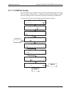
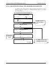
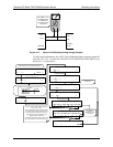
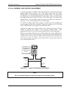
To configure the analyzer’s three analog outputs, set the electronic signal type of
each channel and calibrate the outputs. This consists of:
Selecting an output type (voltage or current, if an optional current output
driver has been installed) and the signal level that matches the input
requirements of the recording device attached to the channel, see Section
4.13.4.1.
Calib
rating the output channel. This can be done automatically or manually
for each channel, see Section 4.13.4.2 and 4.13.4.3.
Adding a bip
olar recorder offset to the signal, if required (Section 4.13.4.2).
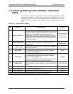
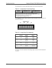
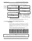
In its standard configuration, the analyzer’s outputs can be set for the following
DC voltages. Each range is usable from -5% to + 5% of the nominal range.
Table 4-16: Analog Output Voltage Ranges
RANGE MINIMUM OUTPUT MAXIMUM OUTPUT
0-0.1 V -5 mV +105 mV
0-1 V -0.05 V +1.05 V
0-5 V -0.25 V +5.25 V
0-10 V -0.5 V +10.5 V
The default offset for all ranges is 0 VDC.
07272B DCN6552