ix
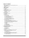
TABLE OF CONTENTS
ABOUT TELEDYNE ADVANCED POLLUTION INSTRUMENTATION (TAPI).................................................................i
SAFETY MESSAGES.............................................................................................................................................. iii
CONSIGNES DE SÉCURITÉ................................................................................................................................... iv
WARRANTY..............................................................................................................................................................v
ABOUT THIS MANUAL........................................................................................................................................... vii
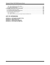
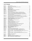
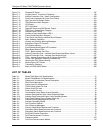
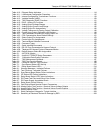
TABLE OF CONTENTS ........................................................................................................................................... ix
1. INTRODUCTION......................................................................................................................................................17
1.1. Features...........................................................................................................................................................17
1.2. Using This Manual............................................................................................................................................17
1.3. Options.............................................................................................................................................................18
2. SPECIFICATIONS AND APPROVALS...................................................................................................................21
2.1. Specifications...................................................................................................................................................21
2.2. Approvals and Certifications.............................................................................................................................23
2.2.1. Safety .......................................................................................................................................................23
2.2.2. EMC..........................................................................................................................................................23
3. GETTING STARTED ...............................................................................................................................................25
3.1. Unpacking and Initial Set Up............................................................................................................................25
3.2. Front Panel.......................................................................................................................................................27
3.3. Rear Panel .......................................................................................................................................................31
3.4. Internal Layout .................................................................................................................................................33
3.5. Electrical Connections......................................................................................................................................35
3.5.1. Power Connection ....................................................................................................................................35
3.5.2. Connecting Analog Inputs (Option 64B) ...................................................................................................36
3.5.3. Connecting Analog Outputs......................................................................................................................36
3.5.4. Connecting the Status Outputs.................................................................................................................38
3.5.5. Current Loop Analog Outputs (Option 41) ................................................................................................39
3.5.6. Connecting the Control Inputs ..................................................................................................................40
3.5.7. Connecting the Alarm Relay Option (OPT 61)..........................................................................................42
3.5.8. Connecting the Communications Interfaces .............................................................................................43
3.6. Pneumatic Connections ...................................................................................................................................44
3.6.1. Basic Pneumatic Connections ..................................................................................................................44
3.6.2. Connections with Ambient Zero/Ambient Span Valve...............................................................................48
3.6.3. Connections with Ambient Zero/Pressurized Span Valve Option .............................................................50
3.6.4. Pneumatic Connections in Multipoint Calibration Applications..................................................................53
3.6.5. Setting the Internal Purge Air Pressure ....................................................................................................53
3.7. Initial Operation ................................................................................................................................................54
3.7.1. Startup......................................................................................................................................................54
3.7.2. Warm Up...................................................................................................................................................55
3.7.3. Warning Messages...................................................................................................................................55
3.7.4. Functional Checks ....................................................................................................................................57
3.8. Initial Calibration Procedure .............................................................................................................................58
3.8.1. Initial O
2
Sensor Calibration Procedure ....................................................................................................61
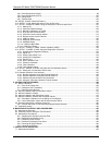
4. OPERATING INSTRUCTIONS................................................................................................................................67
4.1. Overview of Operating Modes..........................................................................................................................67
4.2. Sample Mode...................................................................................................................................................68
4.2.1. Test Functions ..........................................................................................................................................69
4.2.2. Warning Messages...................................................................................................................................70
4.3. Calibration Mode ..............................................................................................................................................72
4.4. Setup Mode......................................................................................................................................................73
4.5. Setup CFG: Viewing the Analyzer’s Configuration Information....................................................................74
4.6. SETUP ACAL: Automatic Calibration ..........................................................................................................74
4.7. SETUP DAS: Using the Data Acquisition System (DAS).............................................................................75
4.7.1. DAS Structure...........................................................................................................................................76
4.7.2. Default DAS Channels..............................................................................................................................78
4.7.3. Remote DAS Configuration.......................................................................................................................94
4.8. SETUP RNGE: Analog Output Reporting Range Configuration ..................................................................95
4.8.1. Physical Range versus Analog Output Reporting Ranges........................................................................96
4.8.2. Reporting Range Modes...........................................................................................................................96
4.8.3. Single Range Mode (SNGL) .....................................................................................................................98
07272B DCN6552


