


60 PI-MTE System Manual Version 4.C
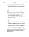
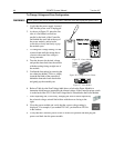
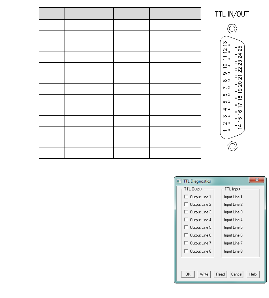
Figure 23. TTL Diagnostics dialog box
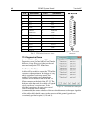
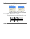
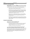
Pin #
Assignment
Pin #
Assignment
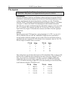
Figure 22. TTL In/Out
Connector
1
IN 1
14
IN 2
2
IN 3
15
IN 4
3
IN 5
16
IN 6
4
IN 7
17
IN 8
5
GND
18
GND
6
EN/CLK
19
Reserved
7
(future use)
20
GND
8
GND
21
OUT 2
9
OUT 1
22
OUT 4
10
OUT 3
23
OUT 6
11
OUT 5
24
OUT 8
12
OUT 7
25
GND
13
Reserved
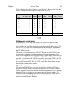
Table 5. TTL In/Out Connector Pinout
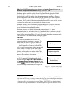
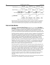
TTL Diagnostics Screen
Note that WinView/32 provides a TTL
Diagnostics screen (located in WinView/32 under
Hardware Setup - Diagnostics) that can be used
to test and analyze the TTL In/Out lines.
Hardware Interface
A cable will be needed to connect the TTL In/Out
connector to the experiment. The design will vary
widely according to each user’s needs, but a
standard 25-pin female type D-subminiature
connector will be needed to mate with the TTL
In/Out connector on the back of the ST-133. The
hardware at the other end of the cable will depend
entirely on the user’s requirements. If the
individual connections are made using coaxial
cable for maximum noise immunity
(recommended), the center conductor of the coax should connect to the proper signal pin
and the cable shield should connect to the nearest available ground (grounds are
conveniently provided at pins 5, 8, 18 and 20).