


24 PI-MTE System Manual Version 4.C
Super VGA monitor and graphics card supporting at least 256 colors with at least
1 Mbyte of memory. Memory requirement is dependent on desired display
resolution.
Two-button Microsoft compatible serial mouse or Logitech three-button
serial/bus mouse.
USB 2.0 Protocol:
PC with Pentium 3 or better processor and runs at 1 GHz or better.
Windows
®
XP (with Service Pack 1), Windows Vista
®
(32-bit), or Windows 7
(32-bit) operating system.
Native USB 2.0 support on the motherboard or USB Interface Card (Orange
Micro 70USB90011 USB2.0 PCI is recommended for desktop computers and the
SIIG, Inc. USB 2.0 PC Card, Model US2246 is recommended for laptop
computers).
Minimum of 256 Mb of RAM.
CD-ROM drive.
Hard disk with a minimum of 80 Mbytes available. A complete installation of
the program files takes about 17 Mbytes and the remainder is required for data
storage, depending on the number and size of images or spectra collected. Disk
level compression programs are not recommended.
Super VGA monitor and graphics card supporting at least 256 colors with at
least 1 Mbyte of memory. Memory requirement is dependent on desired display
resolution.
Two-button Microsoft compatible serial mouse or Logitech three-button
serial/bus mouse.
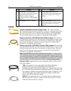
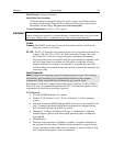
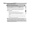
Verifying Controller Voltage Setting
The Power Input Module on the rear of the Controller contains the voltage selector drum,
fuses and the power cord connector. The appropriate voltage setting is set at the factory
and can be seen on the power input module.
Each setting actually defines a range and the setting that is closest to the actual line
voltage should have been selected. The fuse and power requirements are printed on the
panel above the power input module. The correct fuses for the country where the
ST-133 is to be shipped are installed at the factory.
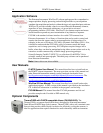
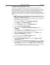
To Check the Controller's Voltage Setting:
1. Look at the lower righthand corner on the rear of the
Controller. The current voltage setting (100, 120, 220,
or 240 VAC) is displayed on the Power Input Module.
2. If the setting is correct, continue with the installation.
If it is not correct, follow the instructions on page 64
for changing the ST-133 Controller's voltage setting
and fuses.
Figure 4. Controller Power
Module