


Chapter 4 System Setup 31
3. Move the slide latch over to lock the connector in place. Refer to "Securing the
Detector-Controller Cable Slide Latch", page 76.
4. Connect the female end of the cable to the camera.
5. Slide the latch until it locks on the posts.
Vacuum
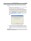
Follow this procedure if you are using the camera in a vacuum chamber. Before
operating the camera in a vacuum chamber, you will need to remove the visible nose that
was installed on the camera before it was shipped. Refer to Appendix D, "Replacing the
Visible Nose with the Open Nose", page 91 for more information. Two cables are used
in this procedure: one for inside the vacuum chamber and the other for connection to the
ST-133 outside of the chamber.
Turn the Controller power OFF (OFF = 0, ON = |) before connecting or disconnecting
the Detector-Controller cable.
The 3' long vacuum-compatible cable is fragile and should be handled very carefully to
prevent wire breakage at the connector ends. Never pull on the cable wires when
connecting the cable to or disconnecting it from the cable connectors on the vacuum
flange, or the camera.
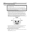
To Connect the Detector-Controller Cables:
1. Verify that the Controller power is OFF.
2. Connect male end of the 6' long Detector-Controller cable to the “Detector” port on
the back of the Controller. Use the 3' long Detector-Controller cable if you have a
2 MHz system.
3. Move the slide latch over to lock the connector in place. Refer to "Securing the
Detector-Controller Cable Slide Latch", page 76.
4. Connect the female end of the cable to the vacuum flange.
5. Screw the connector in place.
6. Carefully secure the 3' long vacuum-compatible cable to the inside of the vacuum
flange. Use a 3/32" hex tool to tighten down the screws.
7. Connect the end of the cable with the slide latch to the back of the camera and slide
the latch until it locks on the posts.
CAUTION
FRAGILE